:bigsmile: I just did get it. My first Super Output Flashlight!!! I’m on cloud 9 now but will be in Hot Water when the Wife finds out about it. It want be the first time I got in Hot Water. :evil:
That’s my only real complaint about the Meteor. I want an interface which includes all levels and lets me quickly go up, down, off, or to/from turbo… no matter which non-blinky mode the light is in. It doesn’t do that. The momentary turbo is really nice though.
Now that I have a Zebralight, it’s sort of similar, but more complicated. And to be fair I don’t love the Zebralights either. The turbo and moonlight (on the ZL) are way too close together for me to like it. I prefer sparks version of the UI with easy access to moonlight and turbo and the ramping through the modes.
Man want to open up one of these Meteors now to scope things out. I think that there ought to be a different UI option on there as well--I am used to it now (the "simple UI") but it isn't my favorite. With some BLF FW options it would be the perfect pocket flooder.
I’ve bugged Zebralight repeatedly about things I think they should do to their UI, but it hasn’t resulted in any changes… and eventually they stopped answering. They don’t like me any more. ![]()
(even simple changes, like making it easy to access other sub-levels instead of the 14+ click method they’ve been using… I really have no idea why they would choose not to fix that, considering the fix is easier to use, easier to code, and should take less ROM space)
Richard, are the 219BT-V1’s you have listed the same as the ones from IOS, or different? I see you both have the same kelvin range listed, but his are listed as SW50 and yours are SW45.
Ok, makes sense. Thanks for the explanation.
Hey, I like my MM15vn and X60vn! ![]()
I probably can’t justify spending as much as I did for the X60vn for another flashlight ever again. That was too much, but it’s a really good flashlight.
Famous last words. Unless you’ve got a really good therapist (or a SWMBO intervening) your drooling over the next super-light will short out your keyboard causing this to happen anyway. You cannot resist- ALL will be assimilated :bigsmile:
And I like shrick’s mention of lower modes being useful; something this ‘newbie’ has had to learn the hard way. Good doing business with RMM, never had better value and service from anyone anywhere.
Phil
I won’t post links, but I wasn’t referring to Vn lights. I saw some custom machined EDC lights recently, and they were going for $400ish tricked out with basically LMH drivers. Jeeze. I get why they’re so much… you know, Because they’re hand made, but I could never justify dropping that.
Has anyone measured the standby current draw of the Qlite e-switch?
I’m modding cheap led lantern that only has a e-switch, plan to use 2x 219C and 4x7135 Q lite driver.
Thanks!
Hi,
I have a couple of the FET+7135 boards plus the parts kit, but is there something/somewhere shows the parts layout for building this board?
I’ve seen a couple of pics on the original thread, but I’m looking for something that identifies which part goes where along with orientation where it matters.
Thanks,
Jim
EDIT: I just found Tom E’s pic in post #149 of this thread:
Is that the correct layout?
Edit2: the layout in that post looks completely different to the PCBs I have :(!!!
Didn’t RMM label the parts he shipped to you? He usually does
This what you are after?
Hi,
Yes, that’s what I was looking for.
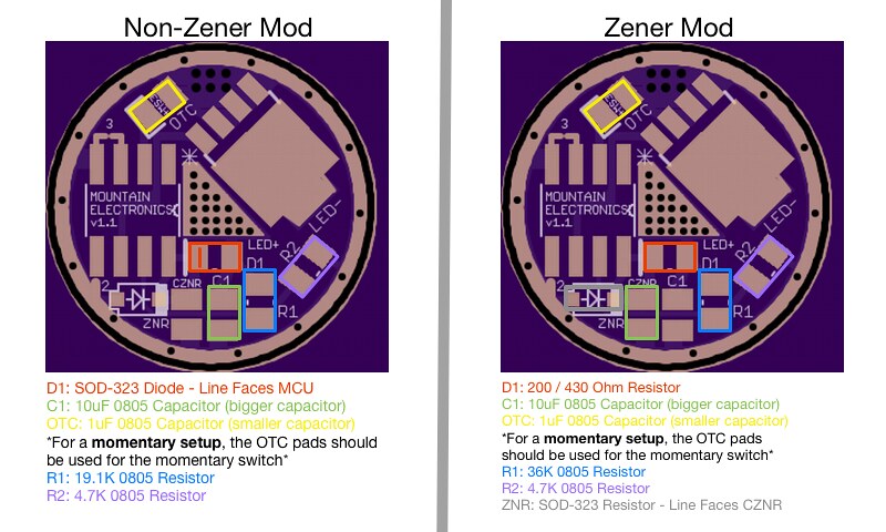
1) So for the non-zener mod configuration, is that diode position under/below the MCU not populated?
2) Which position is MCU pin #1? Is it the one with the *?
3) Where do the + and - emitter leads actually go? Is the + that grid of holes and is the - the tab of the FET?
Thanks!
Jim
Edit: The boards I receive are different… looks like they are 1.0 :(….
1; correct
2; correct
3; see 1 or 2 ;)
I think you need to take a picture of your boards! H)
..sorry, obviously the picture I posted is not the Fet+7135 board.
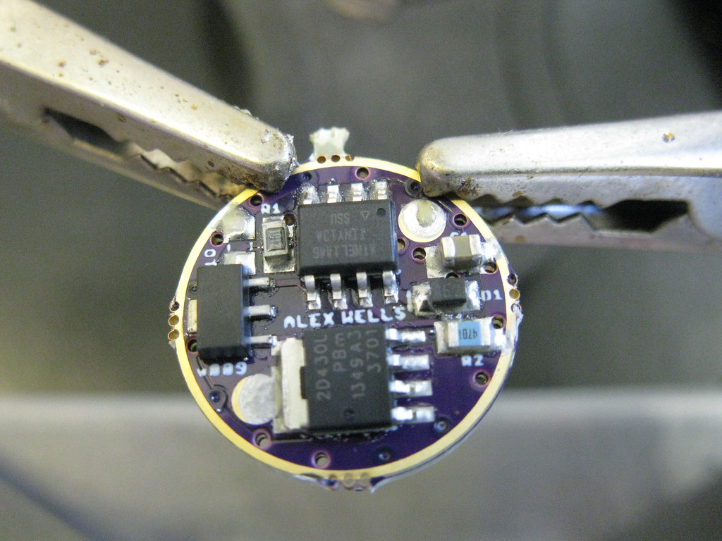
I have a populated Wight Fet+7135 that I can u/load a picture of if it helps.
Here’s what I got from RMM:
and the driver board itself:
FYI, I think that I was able to get one of the boards working, kind of following the layout you showed. I guess that the overall layout (or at least parts) didn’t change much between the FET and the FET+7135 drivers?
Jim
EDIT: In my case:
D1 - the diode in the package - line was towards 7135
R1 - same as yours
R2 - same as yours
C1 - same as yours
OTC - same as yours
ZNR - not populated
emitter + ==> plated area with bunch of holes
emitter - ==> tab of the FET
EDIT 2: RMM was able to flash the MCU with a tweaked version of the BLF-A6 firmware.
Sounds like you have got it under control now :)
The Wight Fet+7135 board layout is different again;