Great news Tom, this can save a heap of trouble and time ![]()
I’m glad you mentioned that Tom E, that was a concern of mine & glad it is being addressed.
Personally, I liked the driver retaining ring and standard size SRK driver much better than the screws and larger non-standard size driver. BUT, I understand the reasoning; so that preference is a non-issue at this point. It is what it is……… ![]()
But what you mentioned above could be a real issue, so thank you for addressing it. :+1:
Please add me to the list for a Q8.
Thanks
I understand completely what you are saying ‘The OnlyDoc’ and it does make perfect sense. :+1:
Proper screw for proper job. ![]()
BUT, that being said; if these boards are made of G10: I pretty much think there is no worry at all . This stuff is tough as nails.
I have used a bunch for knife handles & have two “planks” of it 6.5’ x 8” x 0.5” that I use for car or truck ramps when I need to work under them.
We ran the counterweight end of a forklift up on them to test them out <span class=“floor. off 18” elevated end other & floor cement on plank of end one">
They did bend a very slight bit with the fork lift parked a little past mid way to the top. But it was a very slight bit.
With truck or car they barely even bend at all.
G10…… is tough. Even thin G10… ![]()
Edit for Update from Tom E…. Might be some concern over flat top screws after all. Stay tuned for breaking Q8 news. ![]()
Welcome to BLF!
Will update list later
Hmm maybe somebody already suggested this, but couldn’t a ring be made with the counter sunk screw holes in it, to clamp the PCB down? I’m sorry if it has already been suggested and thrown out onto the curb? ![]()
Talked to two design EE's about the screws as well. Little more concern shown by them. They are more on the line of recommending countersunk holes, at least partial, say'n it would spread the load better, less chance of stress. Neither recalled working with or designing boards with flathead screws, but understood the need in this case. There definitely is some flare out at the top of the hole, so maybe not so bad.
KB - don't think it was suggested. Not sure if we got the clearance, or clearance would have to be made by making the battery ring thicker. Even if they could do 2 oz. or 5 oz. copper on the outer ground trace, that should help - dunno if it's cost effective or possible.
Please add me to the list for a Q8 as well.
Thanks,
John
I’m confused. Are these screws just holding the driver in place until the battery tube clamps it down or are they the primary clamp?
Holding it in place - battery tube is final ultimate clamp, but, screws must be somewhat tight so as not to loosen. The concern was the assembler over tightening with their screw guns - torque drivers are quite expensive so chances are remote they have them. I gotta post some close-up pics of the screws and holes...
My little 10.8 volt Makita drill has tightened at least 3000 terminal blocks and close to a 1000 of #6 to #10 screws. Still use the same clutch settings, I would hope their equipment is at least as good. If those screws are peoples biggest concerns at this point it tells me you guys did a fantastic job making the Q8.
With flat head screws in countersinks the screw will self center into the countersunk hole, this will guide the PCB into position. With more than one screw the screws will over constrain the position of the PCB . To center the LED with respect to the reflector and or center of the flashlight the position tolerance of the threaded holes in flashlight, and countersunk holes in the PCB will have to be held very tight (driving up cost).
The LED position when soldered in place will have to have tight position tolerances as well with respect to the countersunk holes to have everything line up. At assembly there will be little if not any chance to adjust the position of the LED
The pan head screws offer more adjustment to align / position the LED at assembly.
Paul, they were referring to the driver pcb, not the copper board the leds are on.
If i understand it right we have 1 maybe 2 problems with the driver.
If the project wants to go further with the actual design we have to adress the wear problem on the outer ring. Depending on the edge condition and how tight you srew in the tube the wear will be different on every light. Some will have no problems or it will take a long time, some will have problems faster.
And second the srews maybee need some addressing. Depending on who you ask.
I do not have a easy solution for the ground ring wear problem but countersinking the PCB would make a big difference in spreading the load. Still aligning the two holes in the body with the two PCB holes must be very good. If not the load on the edge woud be even bigger because the srew would make contact only with a part of the edge. But when done right it should be fine. Not my prefered solution but it would work (i think ;)).
If the project would go back to the retaining ring the wear problem would be solved because the ring would be the point that makes contact with the tube (if i understand it right). And then the only issu would be to raise the inner positive contact point up 1 or 2 mm to prevent shorts.
It may seem that i am pushing for solution 2 (maybee a little sorry cant help it ;)) but the team and TF has to decide whats the better, cheaper and faster solution.
Let me quote a part of the email we (well I you can tell by the typos ![]() ) send earlier today.
) send earlier today.
If no retainer ring is used I have a nice piece of copper wire with a thick solid core, so I plan on cut to length, flatten copper and solder it to the driver for it to take the wear of the tube.
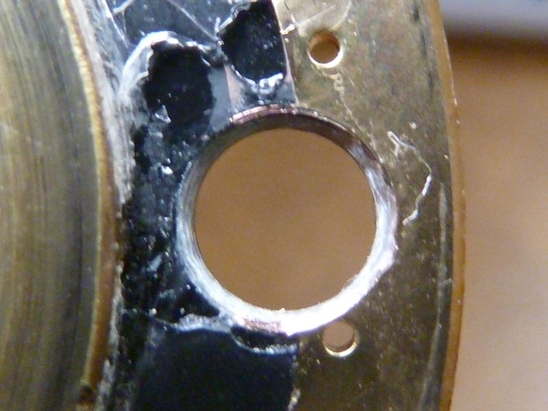
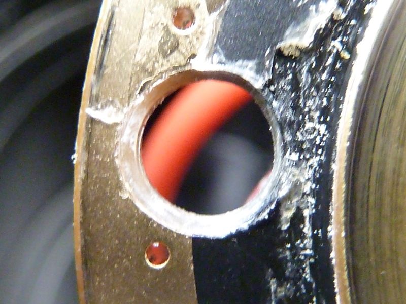
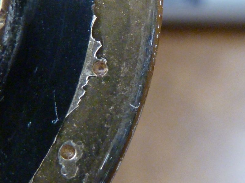
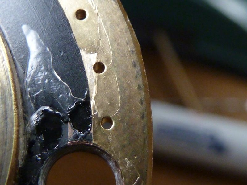
Some new pics showing the screw holes and wear marks. Of course keep in mind about the wear, every other SRK clone (not M6 or new generation UltraFires), and other lights such as Meteor would have this same problem. Many other high quality name brand lights also have their driver glued and count on the battery tube locking down on the driver, but the big difference there is it's not a threaded joint used often - not for battery changes for example. Also this proto has gotten a lot of use/abuse already. With batteries, dis-assemblies, lockout tests, etc. I think you'll see the holes do have a decent bevel. The stuff on the board is the glue remnants from the plastic cover. The first wear mark is the worse I could find.
If they can't convert back to a ground ring, I'm hoping we can ask if this contact area can be improved for durability.
Nice, though probably not needed after thinking it over I think I don’t even solder but just start with that thick solid core copper wire, strip, cut to length, place on driver and tap it flat in the last thread groove with a flathead screwdriver till it is nice and flat and stays in place or would is be better to use solder?
Hard to say from pictures how long it will take for the copper layer to break down. It probably won’t help that the contact region is on the very edge of the board. I think I would just cover the whole thing in solder to handle wear. I would not call this a showstopper but it’s certainly not great design either.
Brass is better than either copper or solder - solder is pretty soft, will wear. Untreated copper has corrosion issues, but maybe the contact with the tube will be enough to keep it electrically conductible? For my own lights, for me it's fine as-is because I can always repair it later. I'd rather see what they have to say to address the issue - there are better solutions - using a heavier trace for example. They may be using 1 oz. copper now, but can go thicker on the ground ring, not sure. Might not add much expense and be the difference of 2 years to 30 years of heavy use - just guessing here.
FWIW, given that the light has very low standby drain and a soft lock-out feature, there isn’t much need to do a mechanical lock-out. I have to use mechanical lock-out on all my other soda-can lights, which all have the same type of thin contact area, and they’ve been fine so far… but on a Q8 it only really needs to be unscrewed to charge the batteries.