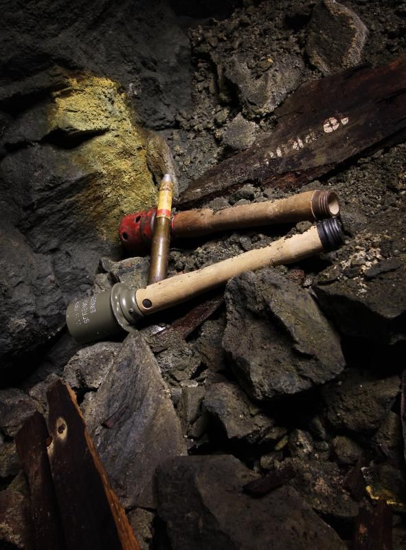
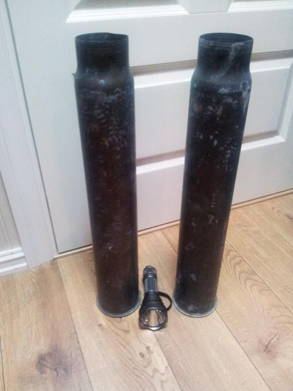
Teaser:
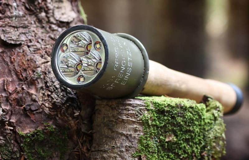
Eine Flashlight head? ja?
Chapter 1 - Introduction
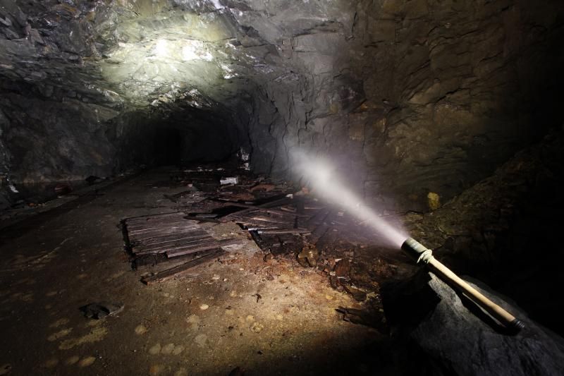
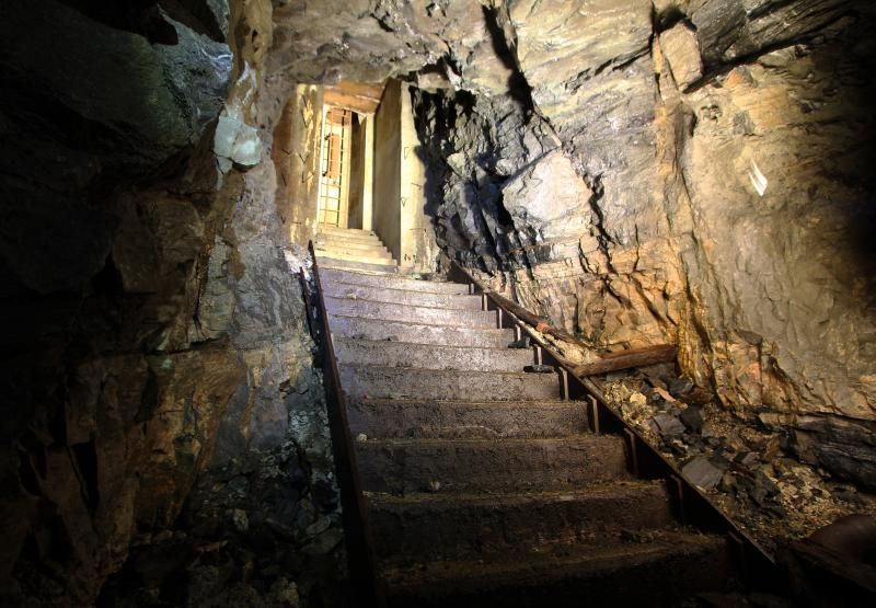
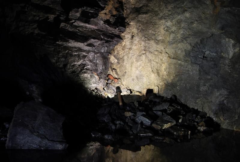
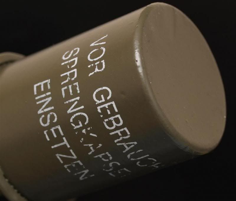
A friend of me who are a bit into flashlights, but very much into WWII stuff wanted me to make a flashlight out of a WWII grenade. This is a replica, not a real collectors item. The flashgrenade will mostly be used for checking out WWII bunkers and such, so I will focus on flood. But Ill also try and implement several things never seen or done before.
I checked with OL before the contest started if I could use these parts as a "base" for my scratch build and he was OK with it. Afterall this is mostly metal and wood and its not a flashlight to begin with.
Chapter 2 - Grenade teardown
Resting on the head of a BTU shocker.


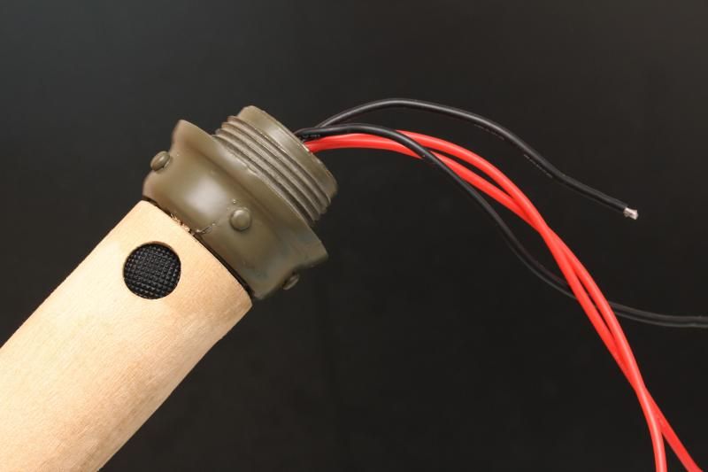
At the tail there is a little hole in it. It does not go deep into the flashlight and its off center.
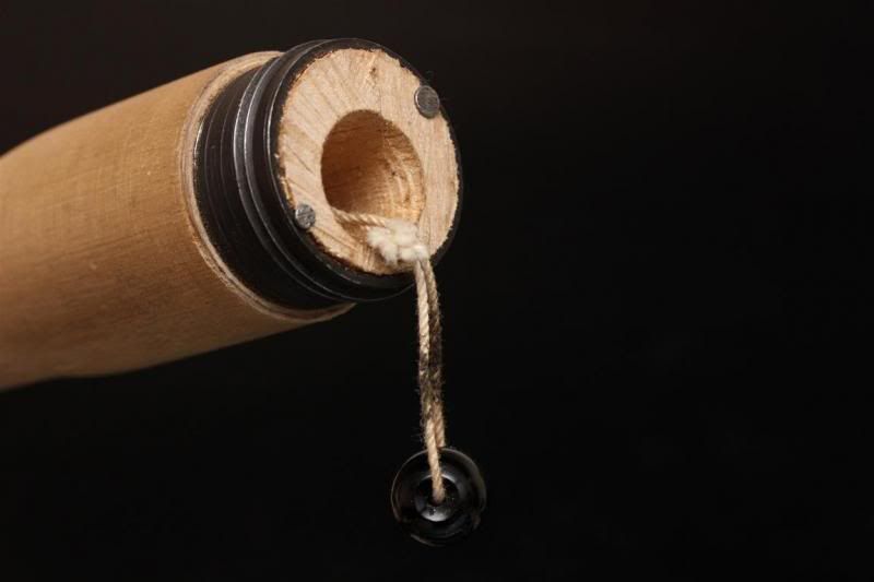
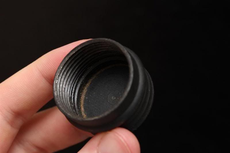
Towards the business end there are some stuff... Which does nothing..
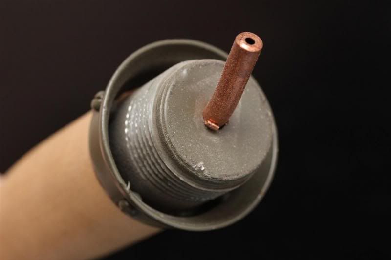
Head is mostly hollow. Its made out of steel.
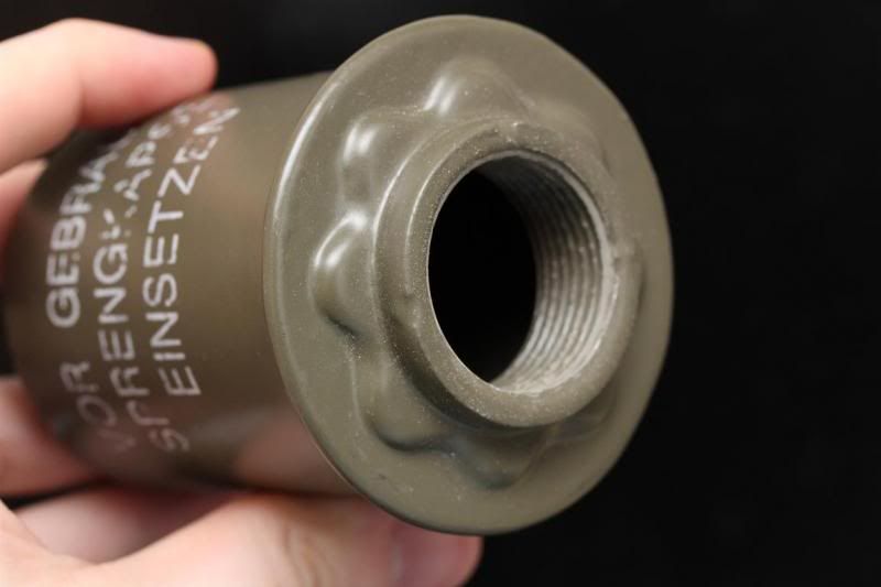
It gave up a little bit of a fight, but I got it apart. Only a minor "fail" to my thumb.
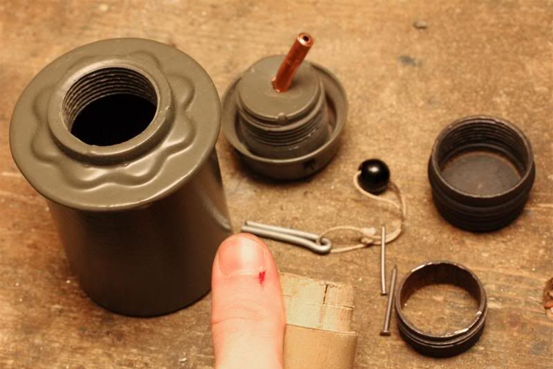
Advantages by using these parts. I got some threads on on the tailcap, and some sort of tailcap.
Disadvantages: I can not mess up any parts or rebuild them. Battery tube made out of wood. Space limitiations everywhere.
Chapter 3 - Got wood
I could not mess up the battery tube. But I had to get space for batteries. 18650 size in order to get some power.
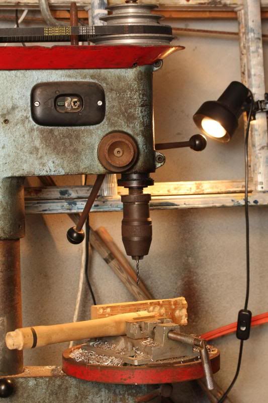
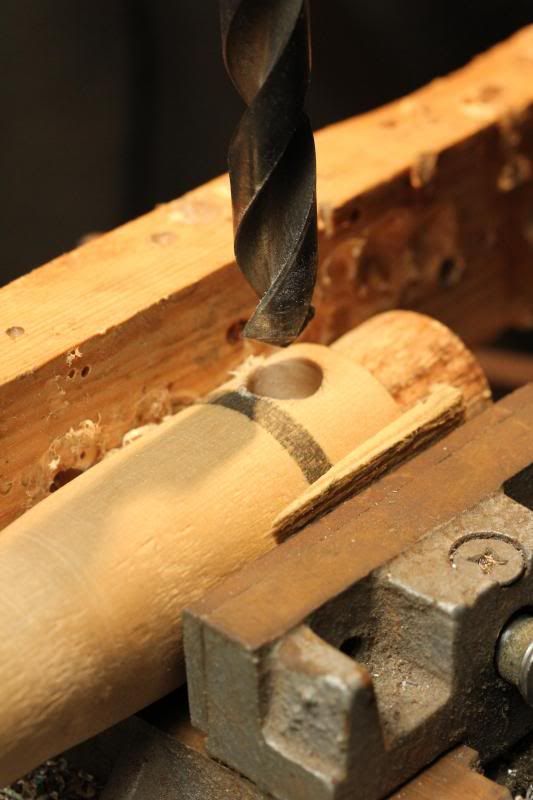
I needed to drill in from both sides, and there was no way to do that accurately with a hand drill or typical drill press. So this is where a lathe comes into the picture. I guess that puts me in the machine made category. Which means, this will probably be the least machine made light. Hopefully it will not look machine made at all. It should look stock. I prefer to do most things by hand too..
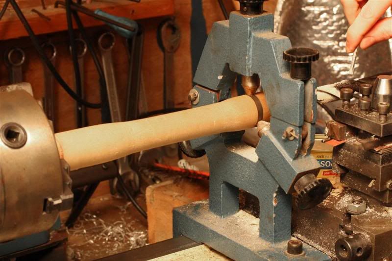
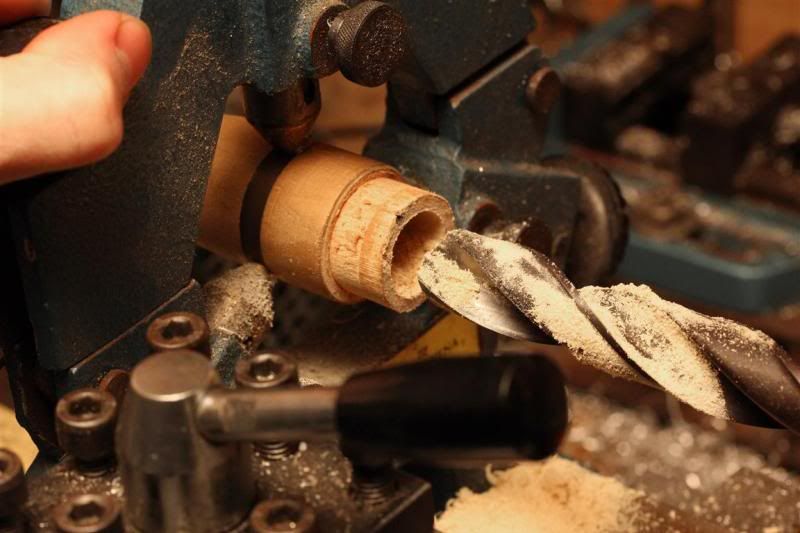
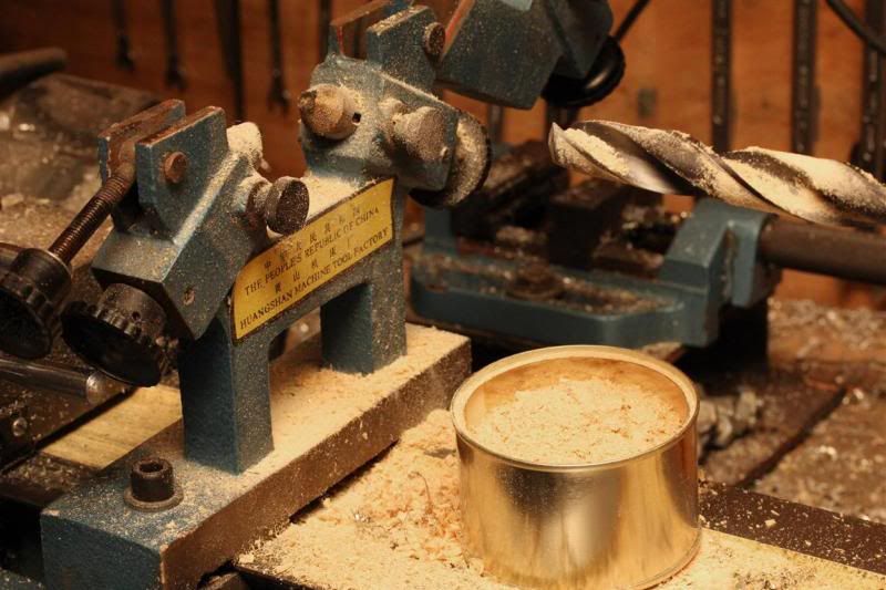
Filled up a box or two with wood dust.
It was a success! Managed to make a nice tube that did not break. Despite drilling in from both sides and despite the off center holes in the battery tube no one could tell it was not done with one super long long drill bit.
Chapter 4 - Electronics
I have done a lot of testing with multi driver setups. After lots of failed setups and lots of time spent on the electronics I found a setup that worked.
Two LD-33 drivers can be used from the same battery source. And they seemed to work nicely. Maybe mode change was a bit unresponsive, but it worked.
3 Emitters on each LD-33.
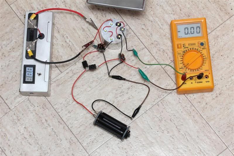
Both on high pushing close to 2,8A to each of the 6 emitters from 3 regular Panasonic 3400mAh cells.
I can set half the emitters to low and half to high if I want. I can mix output just as I want. Most drivers will not handle this properly. LD-33 does. I think LD-29 will do it too, but I never used one for this setup due to its "low" output. I did lots of testing with the FL-2 style drivers too, but never got it to work smoothly without any flickering tendencies and such. I also did some planning with Direct drive and a special switch, but this seemed to be the best setup for what I want do do. I wanted to use protected batteries with good capacity, so a direct drive setup would not have much peak output anyway. And with more common cells and a steel head its probably wise to limit peak a bit.
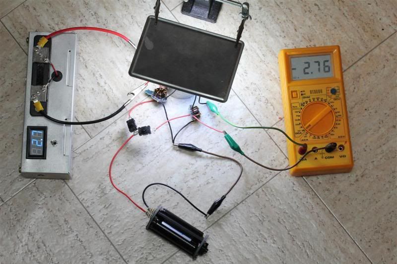
The great thing about the LD-33 is its efficiency. This beats a lot of premium lights and all the typical direct drive setups when using different modes. You can make SOS and Strobe to appear if you want to. Otherwise its a nice 3 mode driver without any blinky stuff. Its also got low battery voltage warning when using 3 cells in series.
Chapter 5 - One triple emitter reflector, 6 emitters
I decided to use the reflector from the Supfire M6. Just because it have a tad more "throwy beam"compared to a SRK. You see, I have plans that will make it into a super flooder too. And I had it laying around. ^^
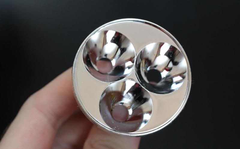
I used some time milling the backside in order to easier get the emitters centered. (work in progress)
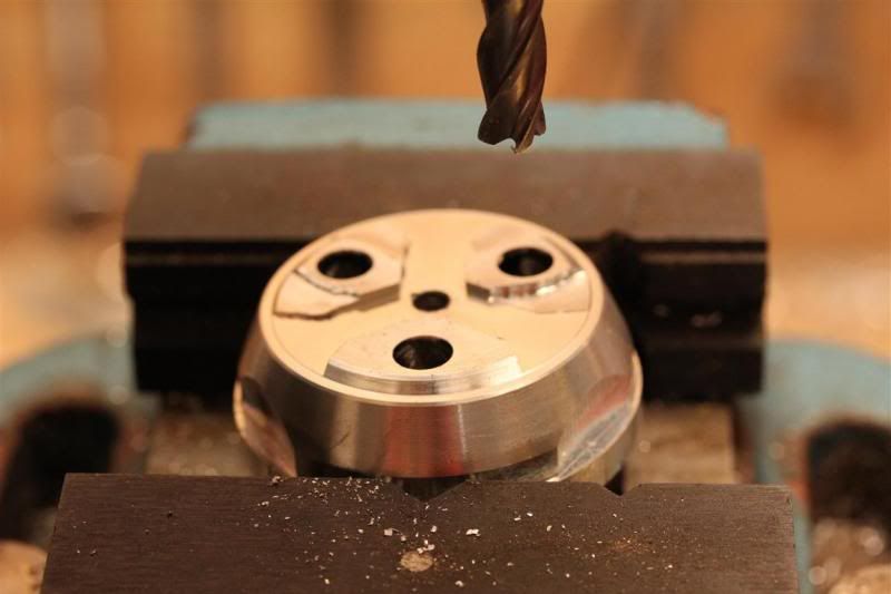
Then I went for it. Making room for another 3 emitters. Super flood style! :)
And I failed at milling extra holes. I tried to use 10mm end mill, should have used 8mm. Reflector still works. Just looks a bit ugly after some failing. I forgot to take pictures. Had to start all over with a new reflector in order to get the looks of a good reflector. Opened up my M6 and took the SRK reflector out of it. I then drilled 3 holes with a flat end mill. With success. But without pictures.
Then I drilled holes to the emitter wires.
Here you can see that there are three extra holes in my reflector. That is where the extra emitters goes. :)
So in some way, the reflector will work as my second pill on top of being a dual tripe emitter reflector.
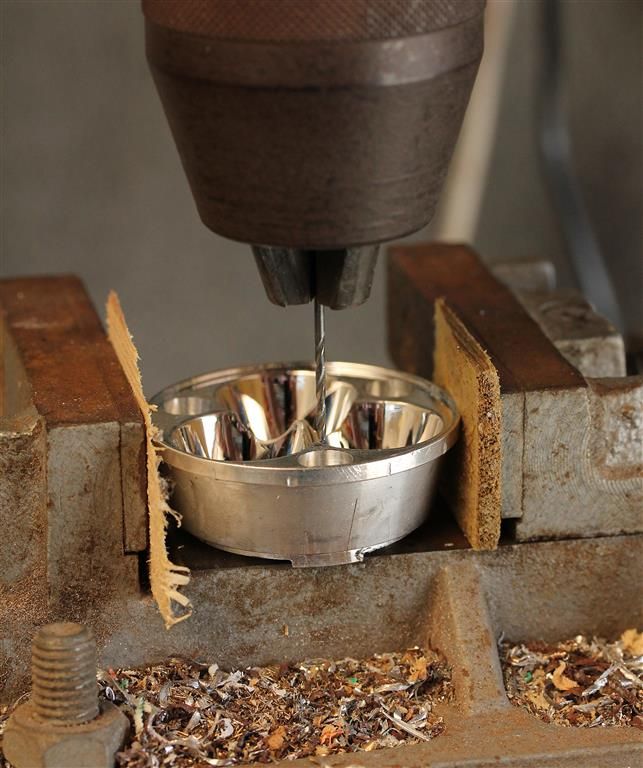
Then I failed some more... Broke of a drill bit... Inside the reflector. :/ Used a ton of time getting it out..
You will get a better look of the reflector in future chapters. :)
Chapter 6 - Tiny copper mcpcbs
I really did not want make the already tiny 10mm mcpcb into someting smaller than 8mm. But I had to do it in order to fit them in the small reflector holes.
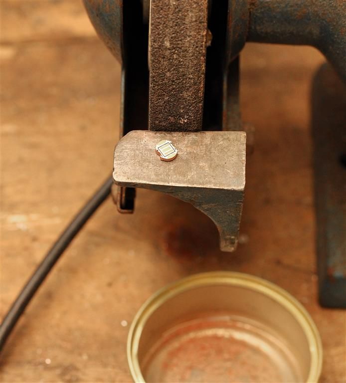
3x super tiny!
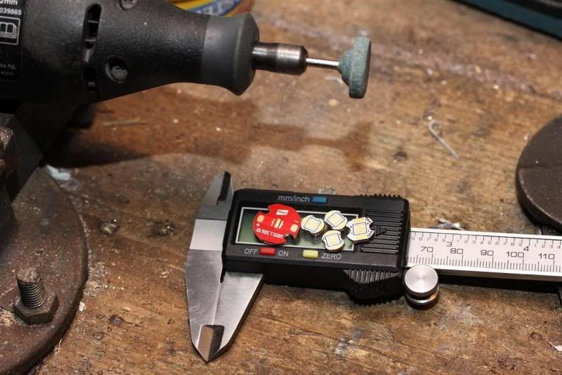
I reflowed the emitters to them and checked that they all worked nicely. Success!
Yay.. Zero fail in this chapter... maybe... to be continued.. Not done with these yet.
Chapter 7 - Next level tint and beam mixing
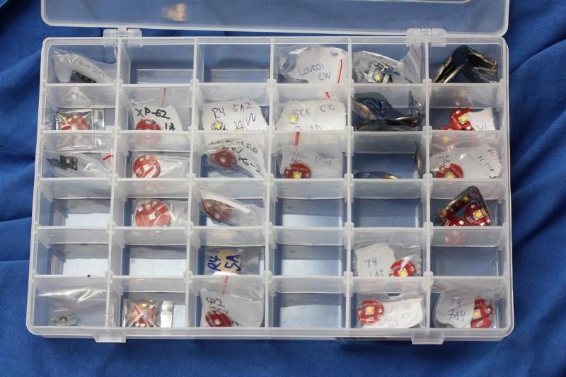
What can I say. Since I started tint mixing I have done it in every multi-emitter light I have done except one. Im not always a fan of it depending on the reflector due to the differences that can be spotted in the outer spill. But in most cases, its great. Here is a thread that goes more in detail on the subject. There are many ways to mix tints depending on what you want to achieve. The general advantages to tint mixing is to make beam with better quality light and less colors. Basically as as white as possible for a certain kelvin.
My setup for this light light is.
Super flood:
XP-G2 WW - (Probably 80 CRI)
XP-G2 WW (Probably 80 CRI) Q2 7C4 90+ CRI
XP-G2 R4 5A2 (70 CRI)
Range:
XM-L2 T6 4C - 75 CRI
XM-L2 T6 4D - 75 CRI
XM-L2 T5 5A3 (80+ CRI)
Why these emitters for this light?
I wanted the super flood to be warm. But not 3000K warm. I also knew that the WW XP-G2s I had were around 3000K and a bit on the yellow side. Above black body locus. Therefore I combined them with a 5A2. Which is below black body locus and NW. My friend likes a bit of WW. Especially indoors and inside bunkers. But im not going for a very warm super flood light. Im normally using a tint mixed SRK with around 3900K for bunker use and various stuff, and its great. Since these are pure flood, I expect them mix nicely.
For "range", I wanted a nice NW. When I say range, that means more than a few meters.. :p Me and my friend also prefer NW for outdoor use. He mostly uses a "5" tinted light for various stuff unless he is using one of his Led-Lensers with CW emitters. Something he is not a fan of. He pretty much likes all NWs.
4C + 4D should be great. On top of that I added a what I consider to be a special emitter with T5 bin and 80+ CRI. This emitter by itself is great. Combined with the two others I expect the beam to look sweet and to raise the CRI a bit. Im usually sticking to emitters that have a quite similar tint and temperature in SRK and larger reflectors triples. This is to avoid color differences in the outer spill.
Mixing two completely different tint-mixed beams.
With the driver setup shown in chapter 4, I should be able to mix these beams exactly as I want. Not sure how it will look with a warmer outside spill, but I think it will be pretty cool combining them. Changing beam character and temperature. They should look great by themselves. Hopefully it will be epic playing around with them! :)
I case people did not notice. The "XM-L range" set have two emitters below black body locus. The super flood set with XP-G2s have two emitters above BBL. For indoor and a bit warmer tints I prefer to be a tad below BBL. Since the XM-L2s have higher output, and will probably be used on a higher output setting Im having high expectations to the overall tint...
Enough tint snobbery...
Chapter 8 - I hate small mcpcbs
This wasn't supposed to be a chapter. Wiring up these small tiny mcpcbs should be easy.
The wire holes I had drilled in the reflector were large enough for 22awg wires. I modified the mcpcbs a bit more to fit the larger wires. But the large size and stiffness of the wires were not preferable. So I went for thinner wires.
The clearing margins from the emitter wires to the reflector wall is tiny. But compared to the space between the dialectic layer and the copper below it in the mcpcb its like a mile.
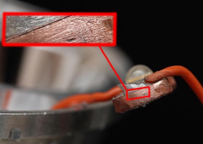
If the solder to the wires just connects a little bit the the cooper in the mcpcb its a fail. And guess what.. I failed, several times. One of the emitters shorted to the mcpcb. I decided to make a new mcpcb since I was not able to fix it (easy fix if you use magnification or take close up picture and see where the error is).
Started on my 4th 10mm mcpcb. Grinded too fast and too much. It got caught up and went flying. Fail.
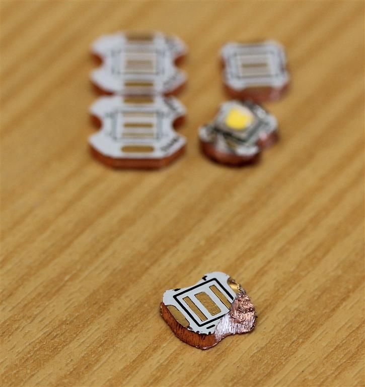
Luckily I had more. Made a 5th and got the emitter mounted.
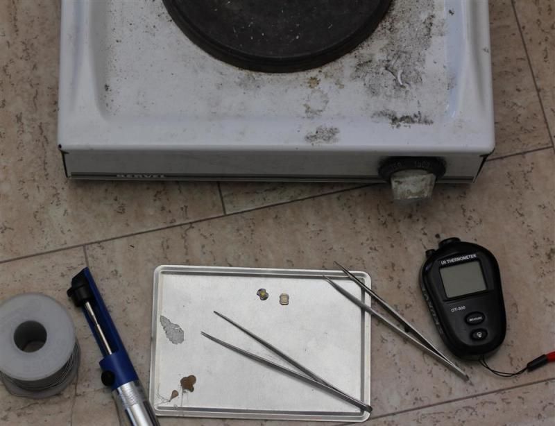
That ended up as a fail because the wire soldering connected to the copper in the mcpcb once more. But I was able to fix it by taking some pictures and grinding off the right part.
I almost left out the part where I at one point had already put fujick on one of these and let it dry in the reflecor before discovering another fail. So I had to get it out and do a bit of cleaning. Lots of testing with the DMM were done checking everything were good and finding issues.
Sometimes easy tasks like installing 3 emitters becomes a PITA. Especially when everything is customized to have tiny clearances.
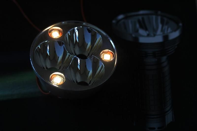
BUT, behold. I have 3 emitters now working in a 3 emitter reflector. And I have not even put emitters in the regular place. :)
Chapter 9 - Opening the head
I knew it was a risk. Trying to open up the head in the late. There was not much to grab. But I gave it a shot. Worked well until..
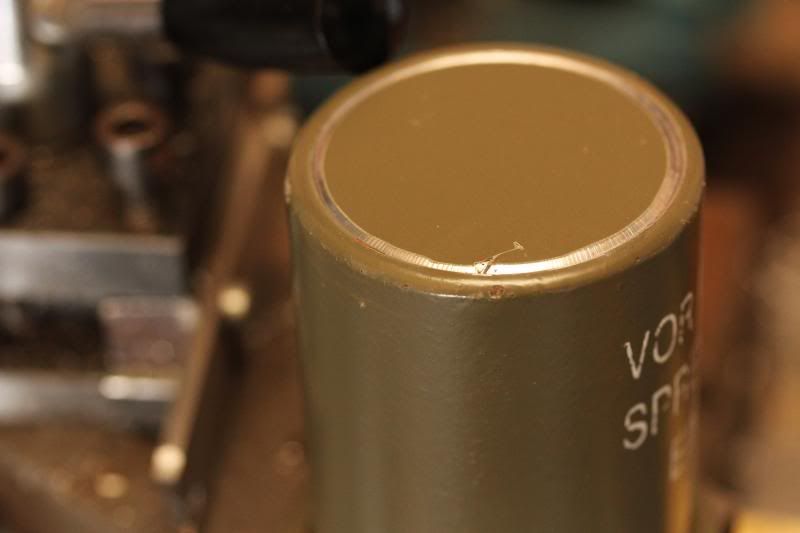
It caught up and went flying... FAIL. I dropped that idea.
Over to the drill press... I managed to drill a hole and failed while doing that as well. I managed to break a 5,5mm drill bit. Reason being I had only attached the bottom off the head. (Its only a ring there.) So it went flying again. :D Should have secured it closer to the top. Live and learn.
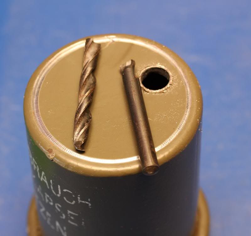
Oh well. Over to more "basic hand tools"...
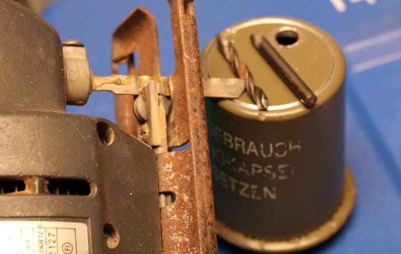
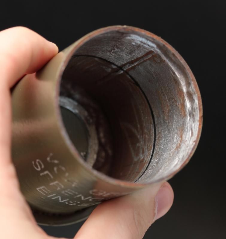
I got the head opened up and worked my way outwards. Using a lot of time with the dremel and various tools in order to make a nice even round hole. Almost done..
Then I failed. Or, the head failed.
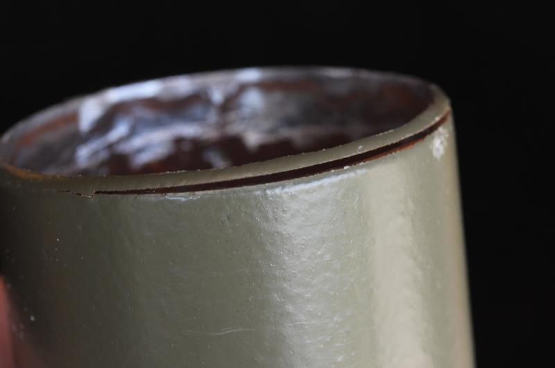
The head top was welded on it seemed. And when I grinded down the welds it got loose.
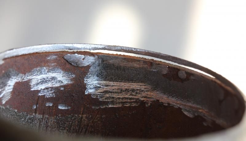
All the work I put in making a nice round ring by hand was no good. The good thing now is that I had perfectly round edge. The not so good. Its ugly, flat and rusty..
Did some more work to the head and pill planning.
Chapter 10 - Making the pill
Since I was already in the machine made category due to drilling out the body/batterytube/handle and using end mill to make the reflector. Might as well use the lathe to make a pill.
Not like a pro, but got it done all by myself. Work in progress.
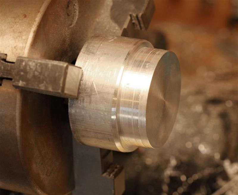
I watched a video on youtube and learned how to use a cutting tool.
Success! A tight press fit. Its a itty bitty tiny bit smaller at the bottom, which makes it a bit easier to press in.
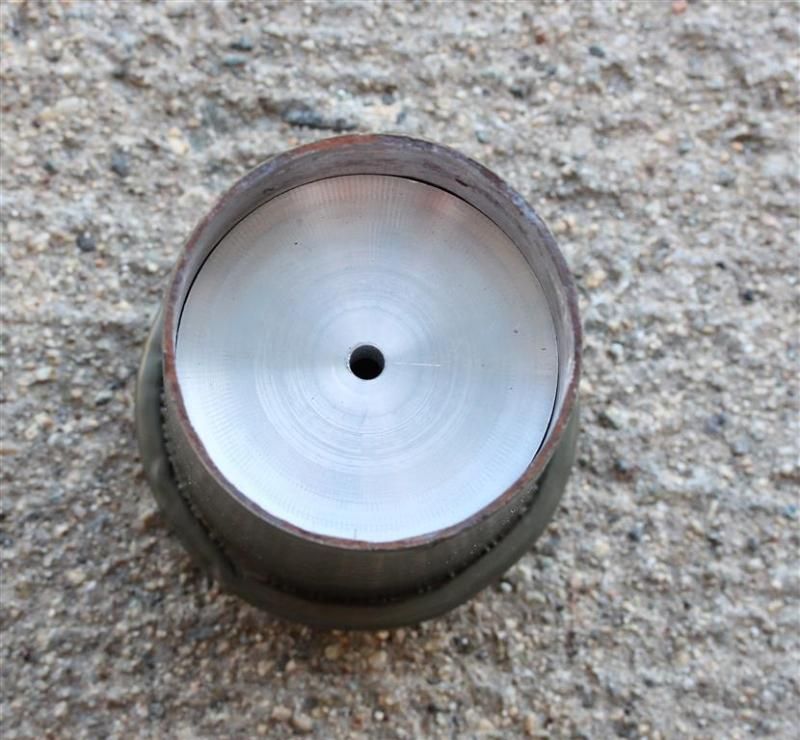
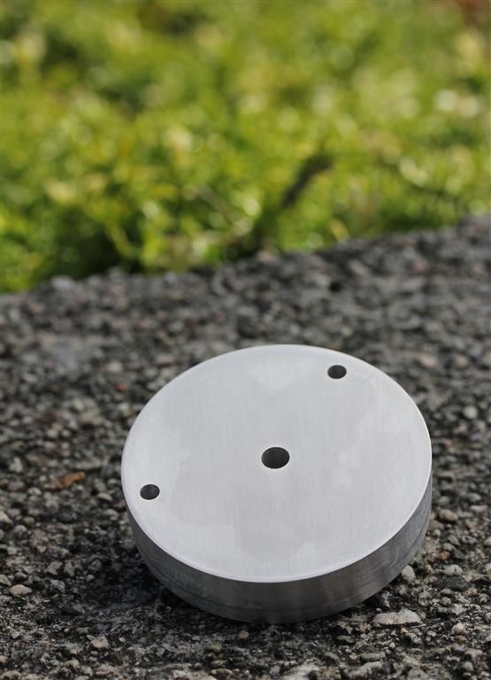
Finished pill just after drilling emitter wire holes and doing a bit of wet sanding.
Chapter 11 - Work that body
What is better than a switch on the rear? Side switch. What is better than a side switch? Two side switches! :D
I cleaned/sanded up the body from the lathe work too. (No dark rings on the front and back anymore)
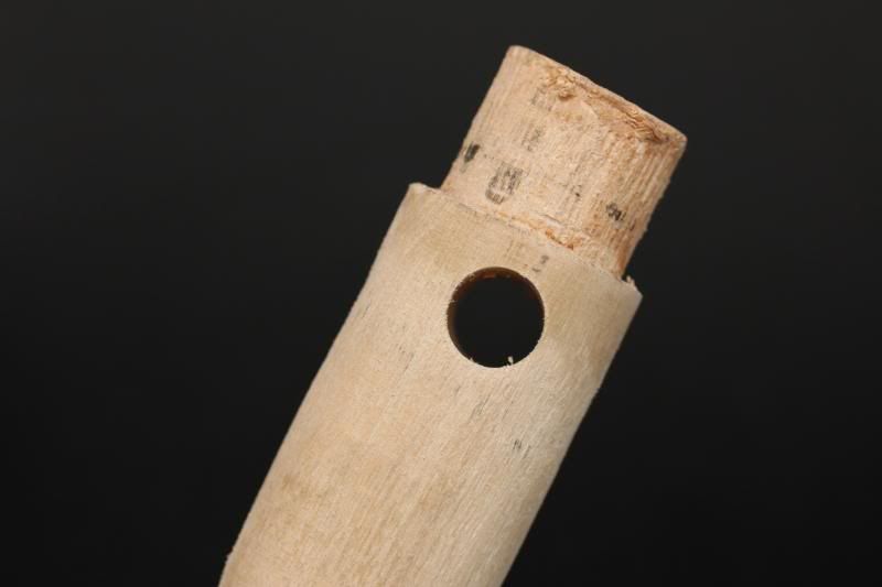
I had used a 20mm drill bit for opening up the tube. My only one near that. Assuming 19mm space for the batteries. That leaves me 1mm. Or about 0,5mm on each side of the batteries. As a negative path from the tail to the front I wanted to use copper sheets. 0,1mm thick. Should be space for it. In theory. But I was not able to bend the sheet nicely. I tried heating and all sorts of things. But whatever I did, it was a FAIL.
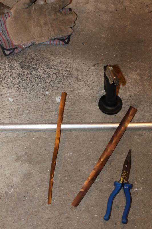
It did not matter if I had thinner nice copper strips either (not pictured).
I tried using a hand file to make the tube thicker inside, but it was no good inside the tube. Or maybe if I had worked it for an hour or three...
But there just wasn't good room for the batteries without being able to perfectly bend the copper sheets and make them stay perfectly bent.
So, I went with something more basic. Wire. I took the isolation of some normal power wire but the wire was too thick to
work with. Another failed plan attempt. Two strings of 18awg wire from IOS was good though. :)
I made a suitable brass ring to connect the wires to. (overlook the black wires on the top side)
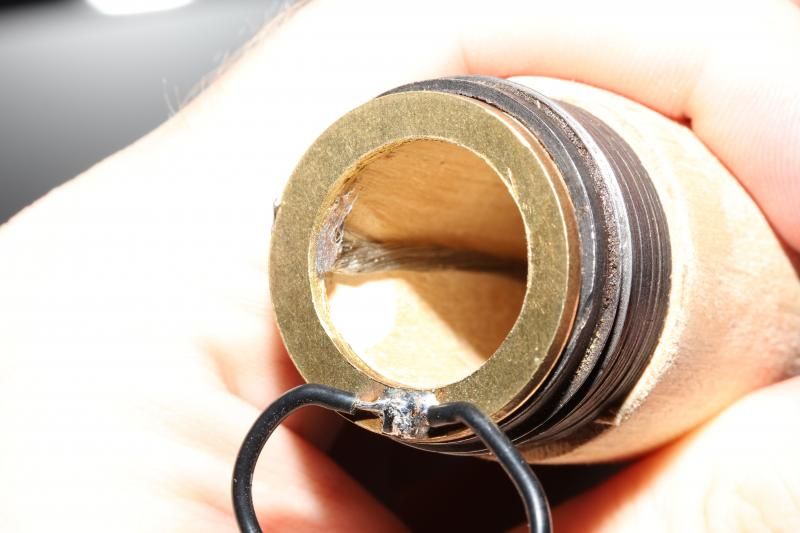
In order to get room for the wires like seen on the picture above I had to do some work to the body.
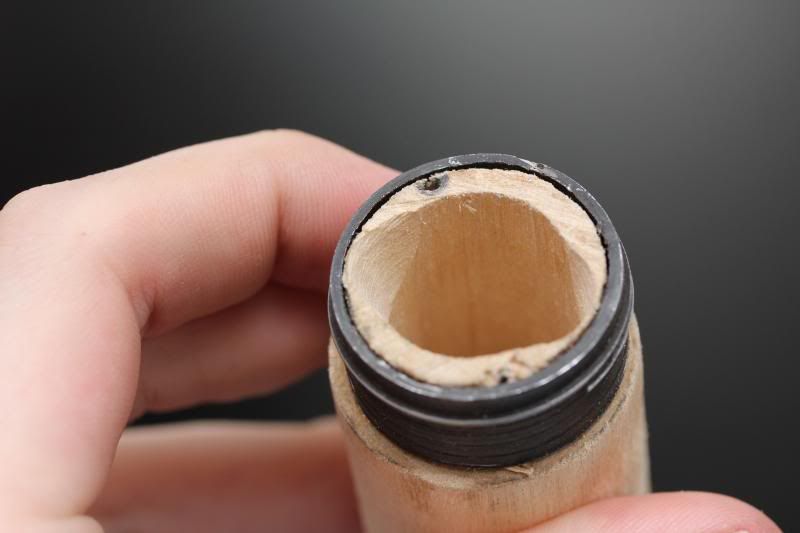
More work where done to the body in order to get in the switch assembly. And to avoid issues with the switch boots.
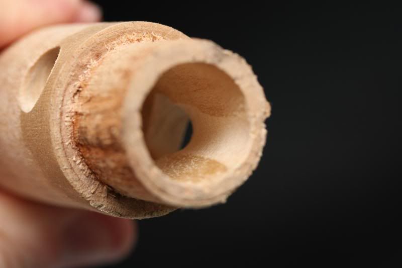
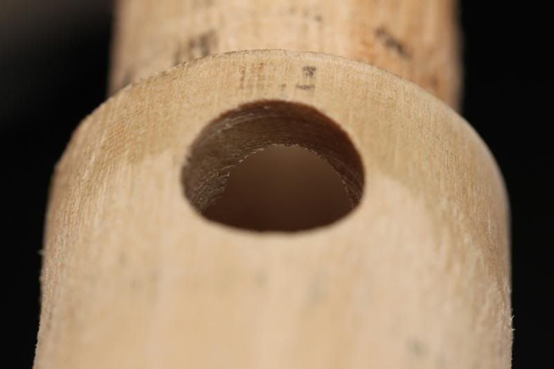
BOOM! Tada.. switches in place... Oh, wait.. That is the next chapter..
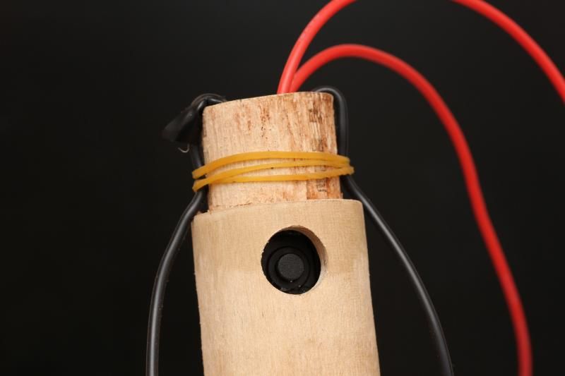
Chapter 12 - Ze dual zwitch zetup..
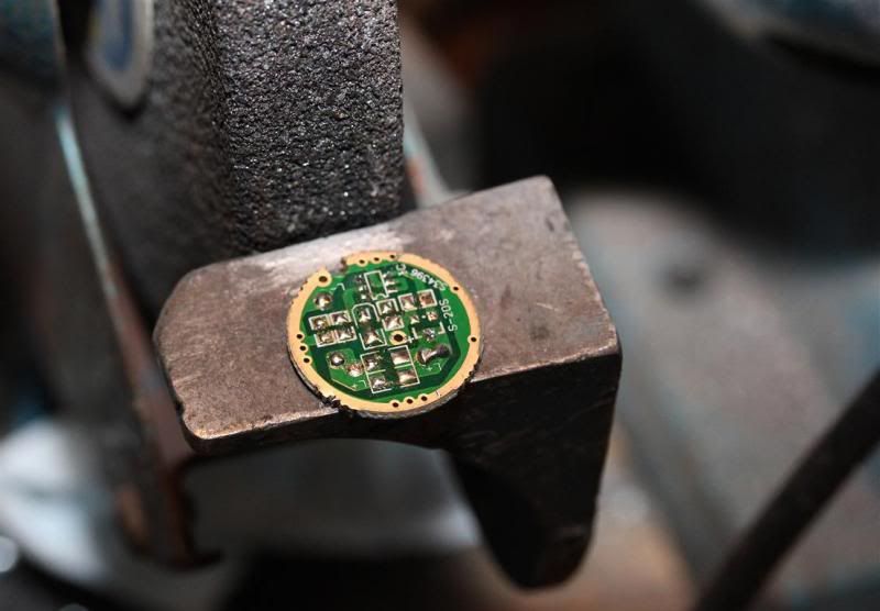
I stripped down a crappy driver circuit that was suitable size. Then I trimmed it so that it was room for the native wires to pass it.
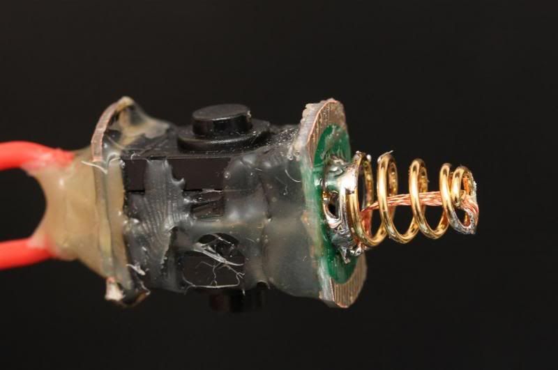
Mixed some parts. and the. BOOM! Like a pro.. Or a three year old with a glue gun. Its actually very solid due to the fantastic glue work.
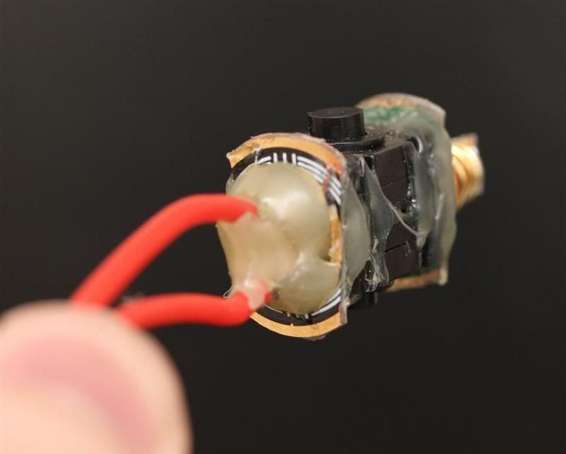
I realized I had several suitable contact boards. So I put one at the back too.
Drilled a hole in the green contact board and soldered the spring directly to the contact board and switches.
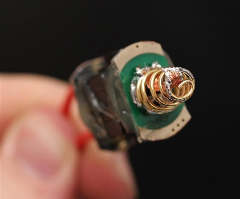
Fits inside the tube like a glove . The fit is so tight that the buttons had to be in the "on" position when pressing the whole finished switch assembly inside the tube.
(picture before I had attached the extra board at the back).
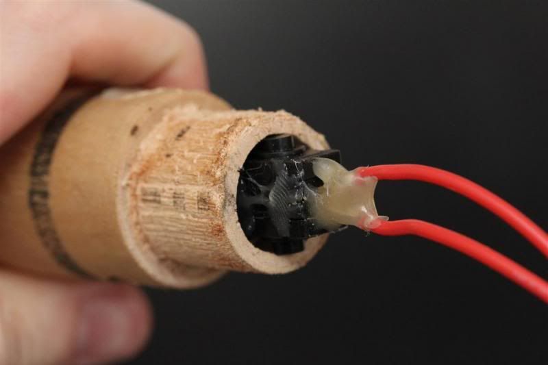
Pretty much in place. :) One switch on each side.

Chapter

Chapter 14 - Tailcap
Some three year old made an attempt at making.. something at the tail.. Prototype.. something.. It can be summed up with one word. FAIL
Its ok to laugh. :D
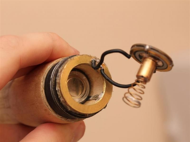
This was the point where I stepped in. 0:)
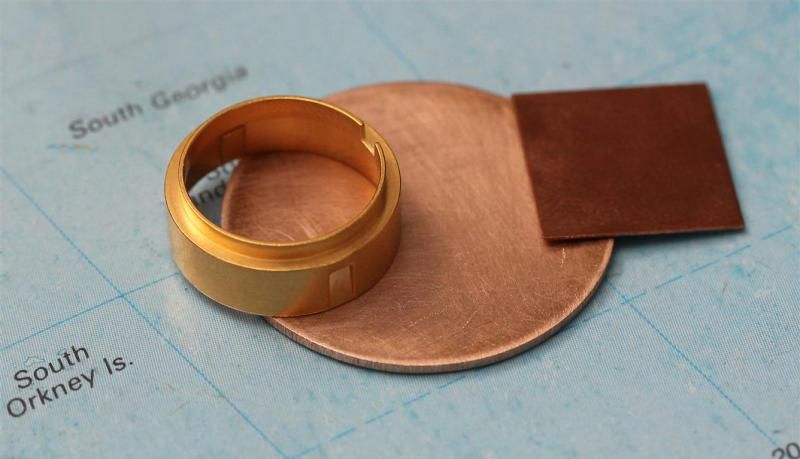
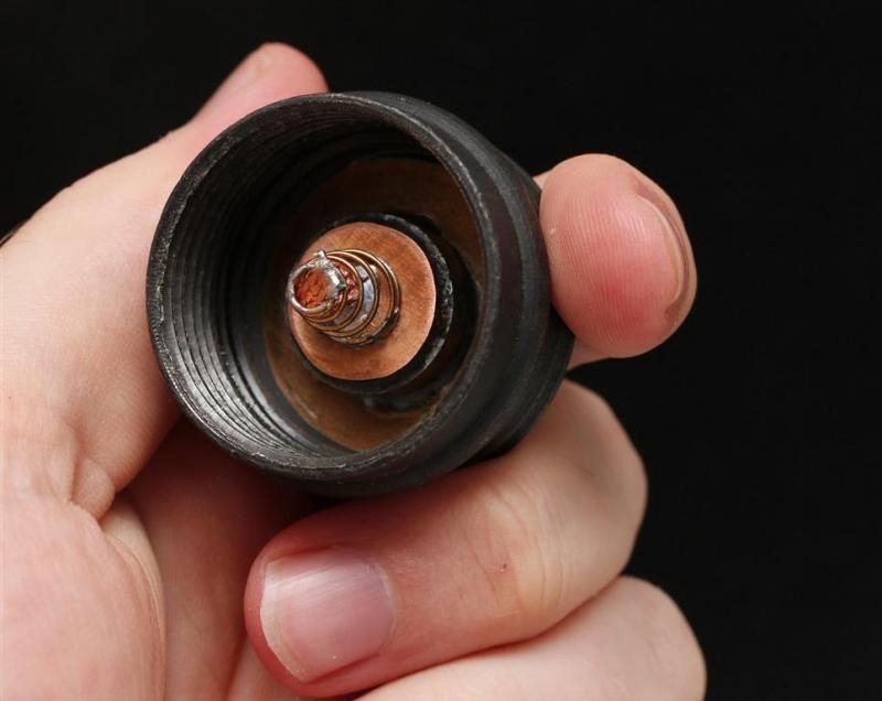
Made this out of a copper plate. 1mm thick.
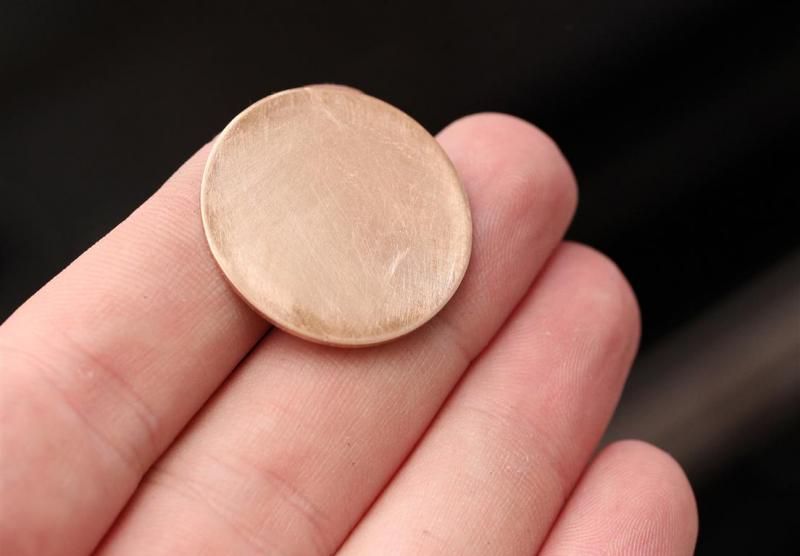
Brass ring + copper shim (for CPU)
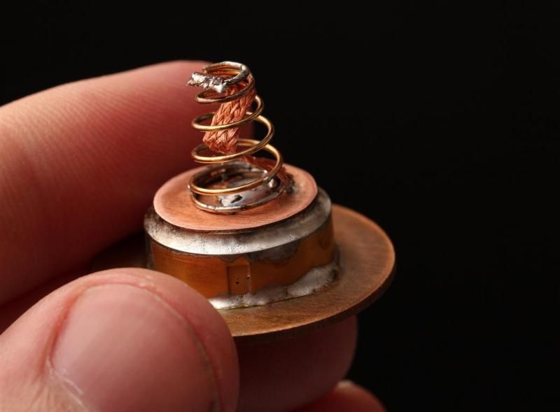
Apply some more grinding, heat and solder.
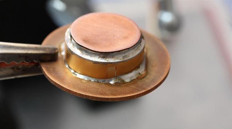
Boom!
Scratched it up, and the tail. Added JB-weld.
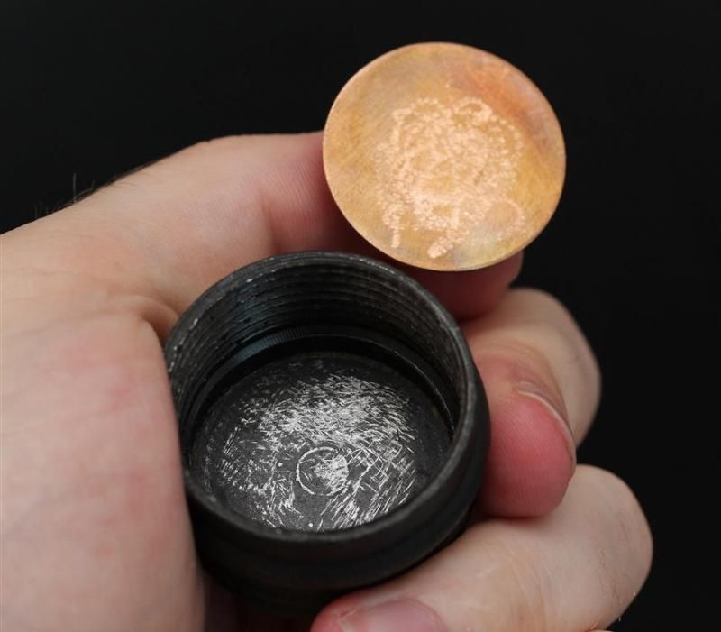
Chapter 15 - Work that body, part two.
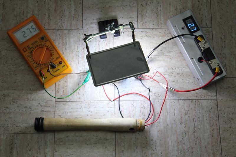
Grenade handle powering up 6 emitters. Through 2 LD-33 drivers. Im running both drivers on high in this picture. Almost up towards 2,8A to each of the 6 emitters (XM-L on alu in this test setup). This is from NCR18650B! (I know, really pushing the limits of those 3 batteries, but I wanted to try). Guess the two 18 awg wires does their job running all the way from the back of the tailcap to the drivers.
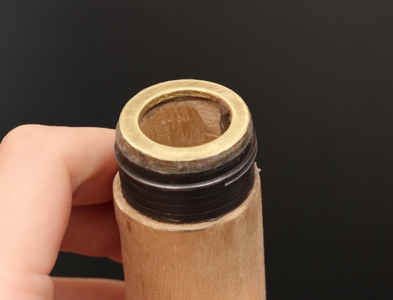
Removed solder from the brass ring I made for the tail. Its held in place by glue and wires. Glue was trimmed.
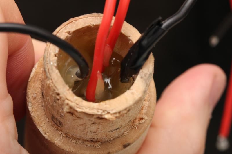
Since everything works. More glue holding the "switch assembly" in place.
Inserted modified boot caps for the switches. Attached the part holding the head (super tight press fit. This is not going anywhere)
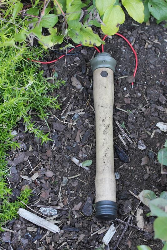
Unlike typical machine builds where lights get polished or anodized. I threw my body out in grass, rubbed grass in it.. Then dirt.. And some more dirt. Working it into the handle. Making it look dirty..
Work in progress:
Chapter 16 - Copper in the head. Because heat transfer..
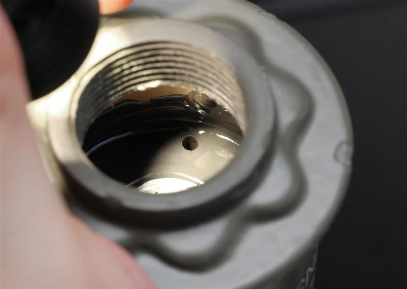
I had a nice aluminium pill now. Fairly oversized with over 12mm thickness. I did not want to make the head unnecessary heavy. I wanted a nicely balanced light. But with a steel head, I wanted to help heat transfer a little bit.
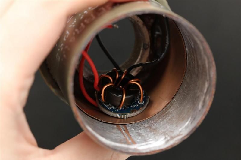
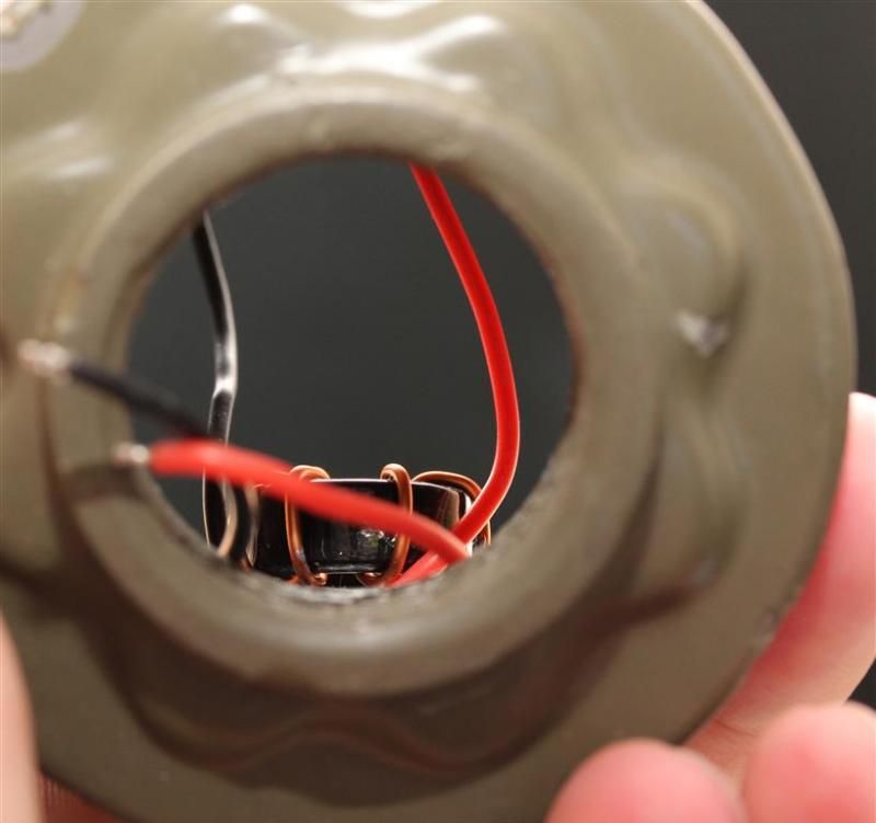
So I added copper sheet to the wall. It was attached with JB-weld. The press fit pill will sit on the copper. Here you will also see how one of the driver circuit sits. Having them sit on the sidewall inside the light transfer heat from them to the lower part of the head better.
One it. Room for two, and still assess to the screw that will hold the reflector in place once its all in place.
JB welded the pill in place from top and bottom side.
Black Tec 7
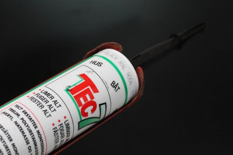
LIMER ALT
FUGER ALT
FESTER ALT
That translates to good S%¤!
I put some on the top of head (made it look nice and black and not rusty).
Pictures in the next chapter...
Chapter 17 - Electronics in a grenade
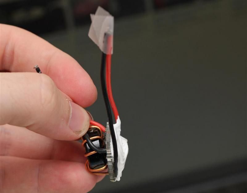
Both the drivers got potted and then attached inside the head with fujick. I should be able to get them out if needed.
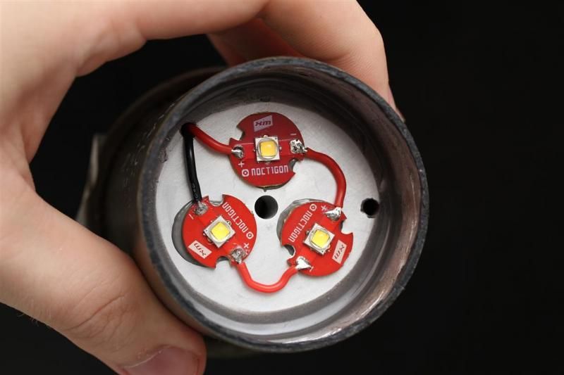
Emitters in place. And no rust on the top of the edge due to the good s%¤#.
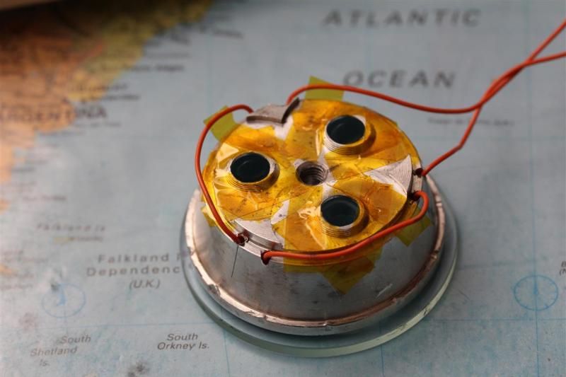
Kapton tape on the backside of the reflector.
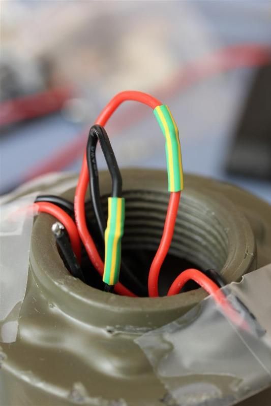
Wired together emitters wires and driver wires (one of the sets).
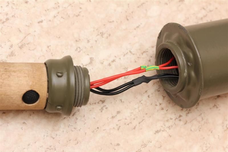
Handle and body united. All the negative wires are connected together. One positive wire from each switch to each driver.
As a temporary solution. I just held the AR coated lens in place with tape.
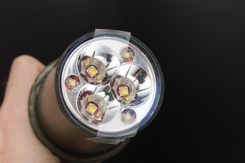
Time to play with the buttons. See if I can get her to power up. And there was light. Glowing bright. Adjustable beams. All in tint mixed perfection with great color rendering. I was thinking on MRsDNF turning on his light going WOOT WOOT. In similar fashion I was gooing WOOT WOOT.. And all sort of strange words not found in a normal dictionary were coming out of my mouth. Lots of photons with high quality unicorn dust attached to them were flowing out of the light in a :party:
I was happy... :)
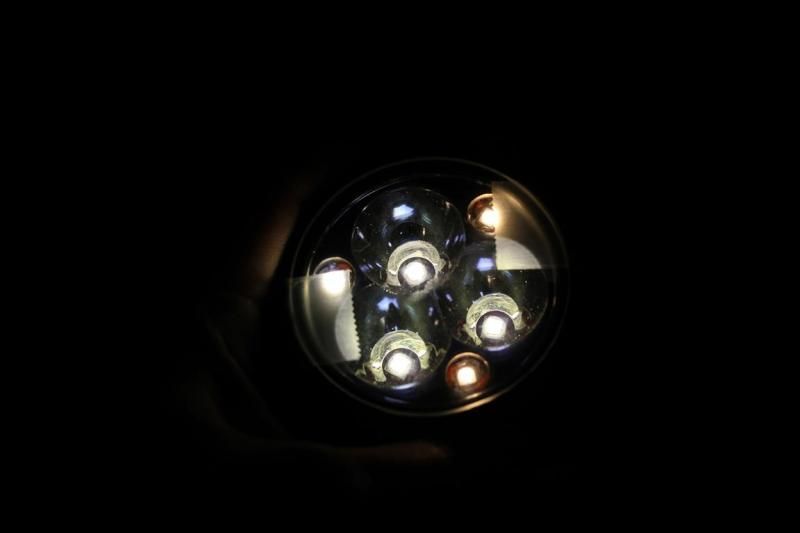
...until she stopped working properly. One of the WW flood emitters were done. Overheated, so much that the emitter was sitting sideways on the mcpcb. Ive only desolderied an MT-G2 with extreme amps and limited cooling before in a test setup. And that kept going strong afterwards. That was not the case with this XP-G2. It was my fault. At the moment of testing the mcpcb was not properly attached (I had to take it out earlier on the day, so the fujick that was on it now was not properly dried. And it had not seen proper pressure when drying like the other two flood emitters). It was a bit loose. So when I tested it on full output, overdriven by almost 100%, it overheated. The fact that the reflector was not transferring heat to the head when playing with it / doing testing probably did not help either.
Fail
Chapter 18 - Let there be light
I found out I had a spare WW XP-G2. I wasnt aware of it, so despite the fail, I was happy to see I had a replacement emitter. Probably one that is even better than the one unknown WW I had in it. I replaced the broken emitter with an XP-G2 Q2 7C4 90+ CRI. This meant my tint plans was still on track. Same temperature and all. :party: Now with even more variety in the emitters and more CRI.^^
The emitter was replaced and properly attached.
Added copper sheets around the reflector.
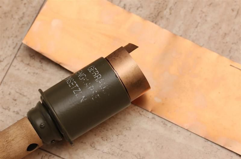
Lots of them. (work in progress)
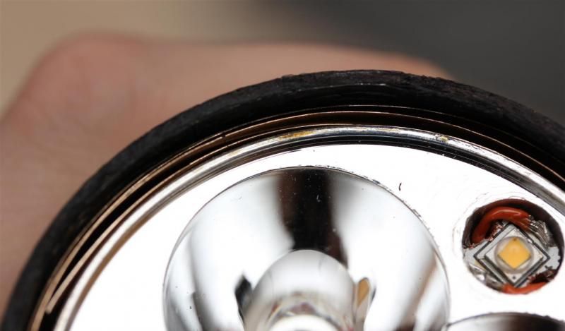
I used Tec7 (the good s%#%) to attach it the lens.
Head is now sealed. And the light is working nicely. Here you can see the 3 flood emitters only.
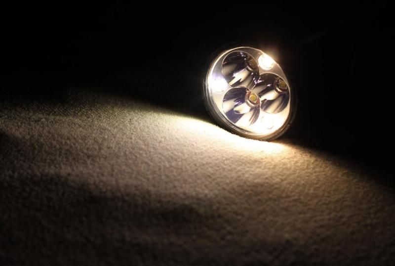
The light is now done! :party:
And its already been used twice this weekend! (Yeah, I was a little bit ahead on the chapter updates)
See next post for feature summary, pictures and videos!
I hope you enjoyed the build.
Thanks for looking.
