Introduction
I have tested a number of UV-leds, but sofar I have been struggling with the method: awkward to perform, not repeatable enough, sensitivity changed during the test, and a recent drawback: no good way to add a ZWB2 filter in the light path.
To be able to use a normal luxmeter, thusfar I made use of copier paper fluorescence, first by making an unstable stack of ledboard-reflector-(filter)-paper-plastic lens, and hovering above that the luxmeter (link), the last set-up was upside down with the paper covering the entrance hole of my integrating sphere (link).
What I like about it is that the fluorescence of copier paper looks to be the same over a range of wavelengths (I will measure the wavelength/fluorescence relation some day), perhaps making it (if calibrated to a known output) for 365nm-400nm leds a measure of radiation power (or more likely: a measure of the number of photons, which is slightly different). I found that a 435nm led hardly causes paper fluoresence, so 400nm seems about to be the upper limit of the method. I do not know the lower limit for this, but since leds lower than 365nm are very low in output and also very expensive, I do not expect to test many leds in this segment.
What I do not like about using paper fluorescence is that there appears to be variation in how much fluorescence copier paper shows per sheet, and that over the course of a test-session some bleaching takes place, so at the end, less is measured than should. Another potential issue is saturation of the fluorescent die: at saturation level light intensities, a noticable amount of die molecules is still in the excited stage when a new photon arrives and so the new photon is not absorbed and a new (blue) photon not generated, this happens at high light intensities and causes the blue fluorescence to be not lineair with the incoming UV intensity. I have not clearly noticed this effect yet but to be honest I have not tried to measure it either.
I did a (not exhausting) internet search of how others have measured the output of UV-leds, and I did not find a better method that could be performed with equipment at a hobby price-point. So what I decided was to stick to using paper fluorescence, but with a better designed set-up, more repeatable, with less bleaching occurring, a filter holder in the light path, and taking into account the variation of fluorescence by different pieces of paper.
What I wanted to include in the measuring set-up is radiation pattern independance, but I have not (yet) been able to figure out a way to integrate UV-radiation without introducing extra (potential) sources of measurement error. So the method assumes a similar radiation pattern for the different leds that are measured. Thusfar all 365nm-400nm leds that I came across have the common familiar shaped dome and the standard ~120 degrees half-brightness angle, so I assume they can be compared this way.
Building the test set-up
Here's what I came up with:

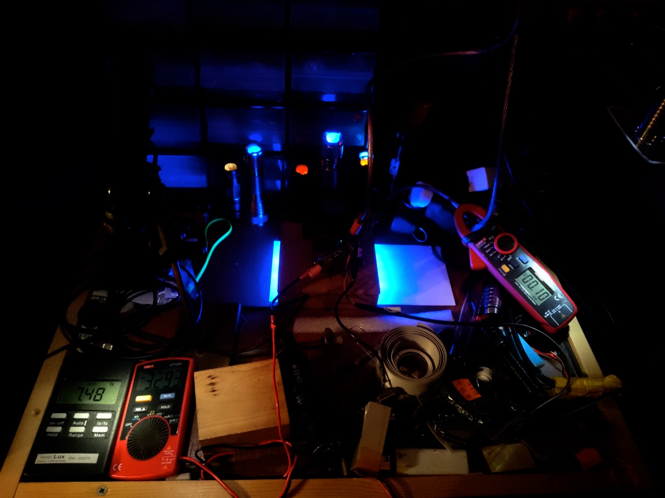
*the piece of paper (not in the picture but during an actual test) covers the 80mm entrance hole of the integrating sphere (btw, the integrating sphere is in this method just used as a convenient already fixed luxmeter, the integration that it also does has no function for this). The led is further away from the paper than last method, causing a 70mm diameter illuminated area on the paper instead of 30mm, which should reduce the bleaching effect by a factor 5.4 , and this also helps avoiding saturation effects.
*over the paper is now a wooden 'bridge'. This makes the paper stay cooler (bleaching may just be enhanced by temperature) and it enables shifting and removing the paper during the test, this helped me measuring the fluorescence difference between sheets, and the amount of bleaching.
*in the wooden bridge is a 30mm hole, which is also the holder for a 30mm diameter ZWB2 filter in case 365nm leds are measured (for an explanation why I want to use a ZWB2 filter for 365nm leds see my test of led4power's 365nm led).
*over the hole is a small wooden shaft to hold the copper led-mount. The inside is covered with aluminium tape to redirect to the paper some of the light that is outside the ~90 degrees cone that is hitting the paper directly, in the hope that the set-up is just a little less radiation-pattern dependent. I'm not sure about the usefulness of this, but I reckon it does not do harm either.

This is how it looks in the measuring situation:

A sketch of how the light is going:
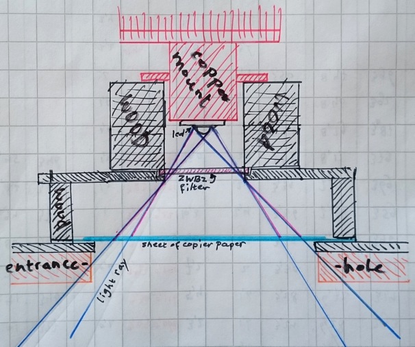
The sketch wrongly shows rays under the paper. Once the light hits the paper, it diffuses and causes fluorescence, this blue light goes in all directions, also through the paper into the integrating sphere and is then measured.
Characterisation of the set-up.
First thing to do was setting up the rig with a led running at a constant low current (checked constant-ness with the luxmeter) and then see what happened to the reading when the paper was shifted or replaced. What I found is that even within one piece of paper the amount of fluorescence varied, curiously over the width of a sheet of copier paper a bit more than over the length, the maximum variation within one sheet, with 15 sheets measured at opposite sides, was 3.7%. The difference between the lowest and highest reading found over the total 30 measurements was 11%, but on average it was much closer. Also a difference between front side up and back side up was found, on average this was about 1%.
(Things you always wanted to know about copier paper but was afraid to ask! ![]() )
)
What I did was write down on the 15 pieces of paper (both ends were measured, so 30 readings) the luxreading with the led at constant output. I calculated the average reading, and wrote on each piece of paper the deviation from the average, which were to become the correction factors for each paper when used in actual led tests. I have now 26 measured and recorded pieces of paper now, so I can test 26 leds before I run out of them. ;-)
I also fumbled a bit with the pieces of paper to see how sensitive the readings were for small shifts and curling up, but that appeared very ok. The position of the 'bridge' over the entrance hole was marked on the top of the integrating sphere with a black marker, shifting that a few mm's did also not influence the reading significantly.
For the moment the unit I use for the measured output of UV-leds is not Watt (or milliWatt), but an arbritrary unit. This is because I do not have a reliable calibration UV-led for this set-up, and the calibration would probably be different for leds of different wavelengths. The calibration is certainly different for 365nm leds which are measured with the ZWB2 filter in the light path. Using the arbitrary unit makes it possible to compare leds measured with this same set-up, and in the course of time I hope to come up with for each measured wavelength (365nm, 385nm, 400nm) a useful multiplier (based on specs of several leds) that gets you the output in mW, also for all previous tests done with this method. (If I would trust the spec-sheet of the Liteon led: 665mW@500mA,25degC, the multiplier for 365nm leds with ZWB2 filter in place would be 16.5. But the voltage in the spec.sheet, which I measured accurately, is at least 0.2V off, so beware...)
In this stage I decided that the method was good to go!
Four leds were measured, of which two new leds and two leds were re-measured for comparison
1) 2)
2) 
3) 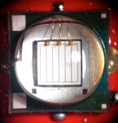 4)
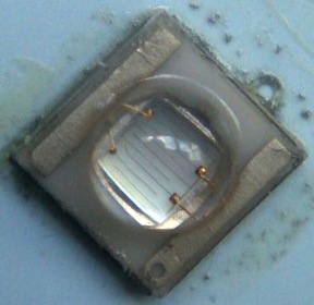
4) 
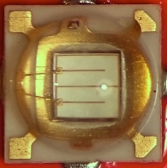
1) Liteon LTPL-C034UVH365 3535 365nm led
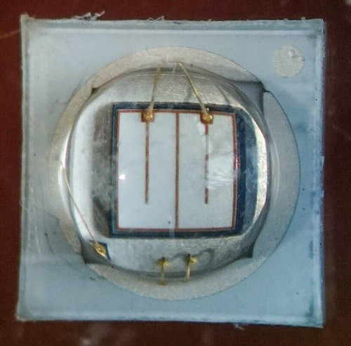
2) Led4powers's 3535 365nm led (with Semileds chip) re-measured
3) Epileds 2800mA 5050 400nm
4) chinese 3535 400nm led from Uniquefire 602C-UV re-measured
Edit: All leds were measured on direct thermal path MCPCB's.
The Liteon led caught my attention because the die looks the same as the well-performing led that led4power sells. I found it at tme-eu. The Epileds led was brought to my attention because The Miller mentioned it in one of his threads, it has (for colour leds) a rare XM-size, with the die (I estimate) of 1.5x1.5mm (XPG-size) and is rated for an impressive 2800mA, which is high for a 400nm led. I found it on aliexpress.
Because the measuring method has changed again, and I can not give absolute output levels, I put two leds into the test that I have measured before: led4power's 'Semileds die' 3535 365nm led, and the chinese 400nm led that is found inside the Uniquefire 602C-UV, that I found to have a very good output for its size.
First the XM-size 400nm led, the specs that I could find were meagre: Epileds, 395-400nm, 8W, radiometric power 80-100LM ( :-D ), voltage 3.4-3.8V, 2800mA, 120-140degrees beam angle. I was very suspicious because the manufacturer did their best to make it look like a Cree led, like the very low performing Latticebright leds. does it really draw 2800mA, and if so, is the output what you expectfrom such a current. I compared it with the ok-performing chinese 3535-size 400nm led from the UF 602C-UV that at best performance stays under 1.5A:
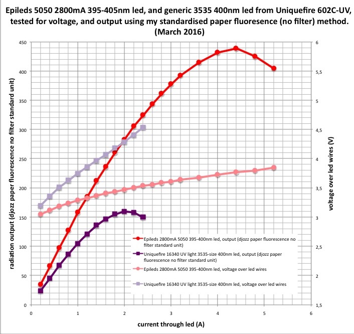
So it does draw well over 2800mA before maxing out, and has an output that matches the power draw, much more efficient as the led in the Uniquefire: higher output with lower voltage, and I think it even that the die has a higher luminance , making it throw better (in case you are into 400nm throw ![]() )! I like this led a lot: the voltage and current sweetspot (3A) is in a great range to use the led with an ordinary lineair driver like the 105C or Qlite, its power is 10W, and the output is very good, perhaps as high as 4W radiometric power (but this is a dangerous estimate not backed up by anything close to a calibration). The die has a good even luminance too which is good for your beam:
)! I like this led a lot: the voltage and current sweetspot (3A) is in a great range to use the led with an ordinary lineair driver like the 105C or Qlite, its power is 10W, and the output is very good, perhaps as high as 4W radiometric power (but this is a dangerous estimate not backed up by anything close to a calibration). The die has a good even luminance too which is good for your beam:

On to the Liteon led. It is in the exact same category as the led that led4power sells, but it costs slightly more. The die, when looked at it, gives off that same lime-ish-yellow visible light as the l4p led. So I expected similar performance.
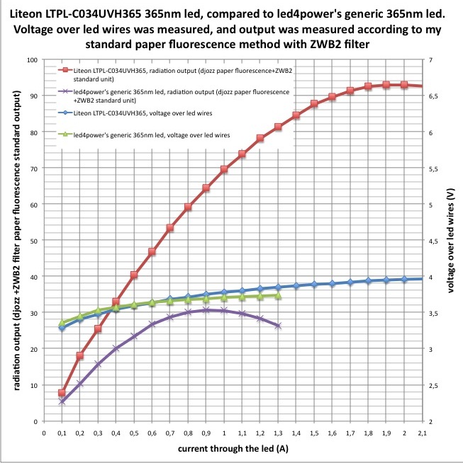
But no, the performance is way different, better!. The voltages are very similar but the output is higher at all currents, and it maxes out at a higher current too, almost at 2A, with 0.9A for l4p's led (in my earlier test, another led from the same reel, the maximum I found was at 1.1A). If the die's are indeed the same, the package has a way lower thermal resistance which could lead to better performance, but perhaps also the die's are different after all. Because of the new method, I wanted to be sure about the better performance of the Liteon, and built it into my Jaxman U1 that could use an upgrade from its medium performing led anyway. I have the l4p led in a BLF-A6 host shortened to 18350 with a 700mA lineair driver, so I shortened the Jaxman to 18350 also and used a 1400mA 101-AK lineair driver. If the led performed as in the test, and the hosts (especially the UV-pass filter) behave similar, I expect 3 times as much output.
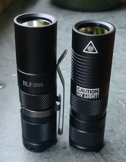

And it does put out much more light, at a measured 1.2A tail current, from the graph I expected 2.8 times as much power and I measured roughly 2.15 times as much power, so not exact, but then: the lights have different reflectors and perhaps not the exact same filter, and the l4p led that was in the A6 might have been a slightly better one than the one tested. This led in the Jaxman is a keeper :-) (on top of that: I like the shortened Jaxman better than the long one, but kind of miss the Jaxman lettering)
The above picture btw was a kind of expensive one to take, I first forgot to protect my phone camera from the considerable UV-radiation from those two lights, which not only made the picture too purple (the final picture was taken with a polycarbonate filter), but now the chip is slightly damaged too, see the following shot of a completely white wall :-( :

Although ending with this sad note, thanks for reading another test! :-)