This is an attempt to keep tech ref info on the BLF17DD driver(s) together in one spot, hopefully easier to reference this way.
----------------------------------------------------------------------------
Note: Post #124 is a great write-up by RMM on voltage divider calculations
----------------------------------------------------------------------------
As of July 12th, 2014:
The new improved 17mm FET based driver here: OSHPark BLF17DD V1.0
It's matching parts list: DigiKey shared cart- BLF-17DD & BLF-20DD Qty 1 (includes a working MOSFET now!)
Post #1045 here in the big OSHPark thread from comfychair has pretty good details on this upgrade. Basically, it's an alternate solution to using the 130 ohm resistor to reduce a voltage spike flatten the peak. Actually this new CAP method works so well, it opens up the possibility of using other FET's.
Post #1077 here in the big OSHPark thread from comfychair explains where/how to do the zener mod on this board, as well as explain where/how to do the off time memory CAP mod.
(Pictures to be added here. Not ordered yet - hope the design is settling down for now...)
----------------------------------------------------------------------------
As of June 15th, 2014: (this is obsoleted now, but still applied for those with the old rev boards)
There are now two version of the BLF17DD: standard and zener diode mod version:
PCB link standard: OSH Park BLF17DD Rev 4 (link not working now - it's been removed to allow no more buys)
PCB link for Zener diode version: OSH Park BLF17DD Zener Rev 2
You don't need the zener version to do the zener mod - it can be done to the standard BLF17DD as well, just little more difficult.
Notes:
- you don't need the resistor for R4 - should work fine without it
- parts as a kit can be bought from Richard here: mtnelectronics FET driver parts kit
- DigiKey parts list: DigiKey shared cart- 17&20DD, qty 10 (thanx comfy!) - could be used for purchasing or reference. Following parts link will get you to spec sheets, etc.
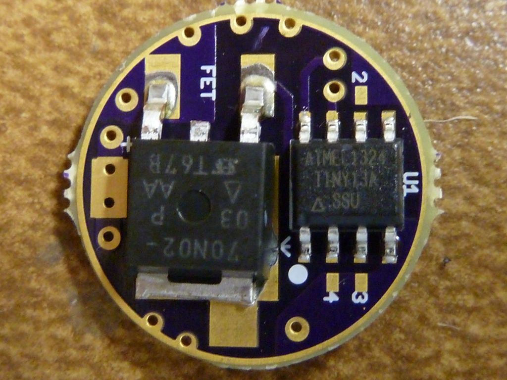
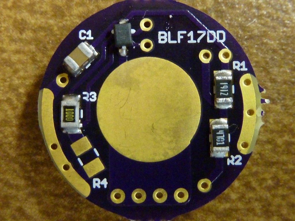
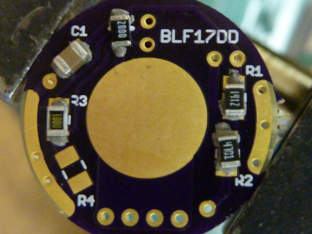
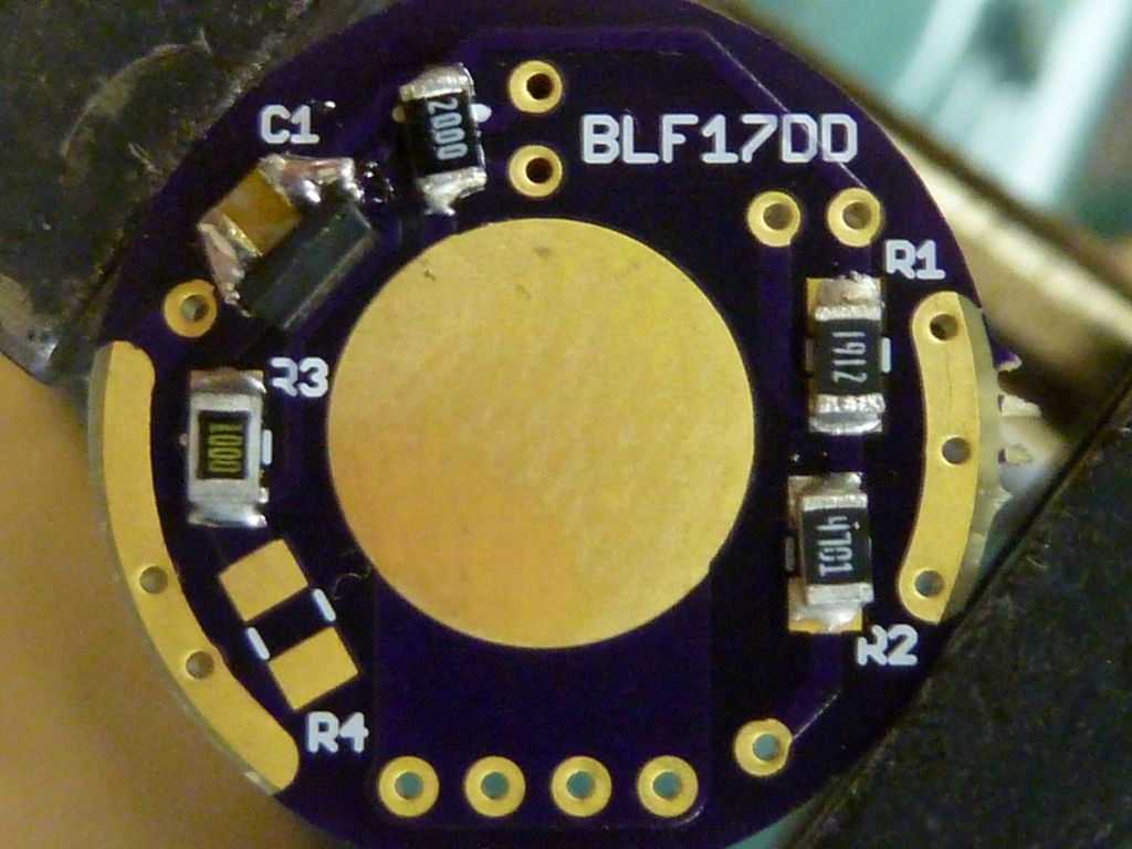
Sample View:
This is a Rev 2 or 3 populated, first top (inside) and second bottom (spring side) showing the parts positioned correctly. Note: I'm using a 100 ohm resistor in position R3, but a 130 ohm should be used for R3 -- it's a better value (100 ohm is borderline). Here:
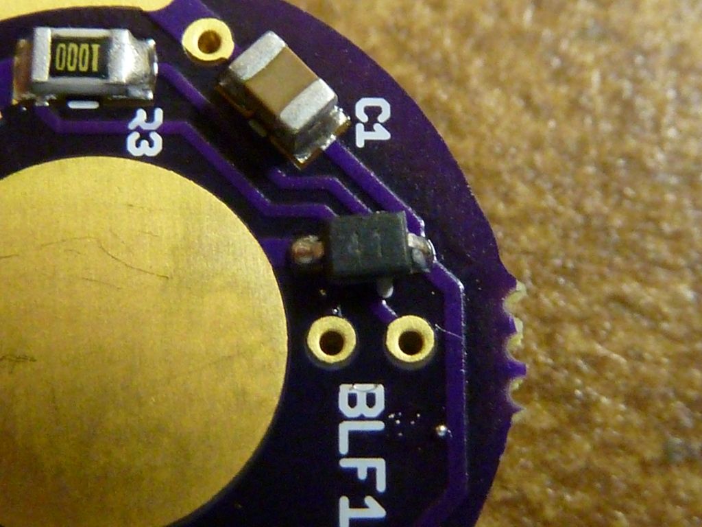
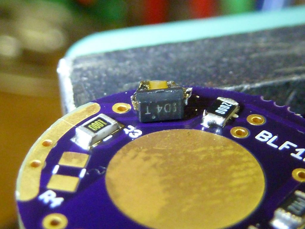
Detail view of the diode positioning:
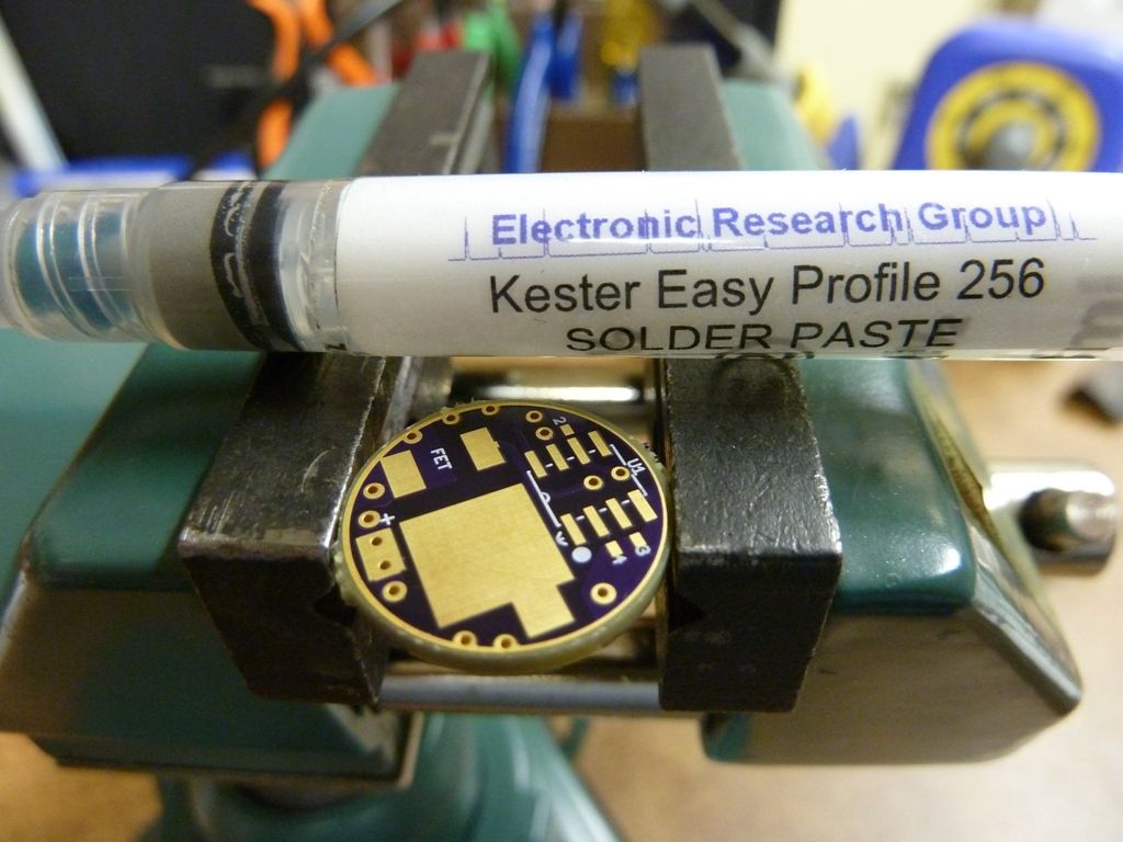
Sample Assembly:
This is the solder paste I use:
This shows the application of it:
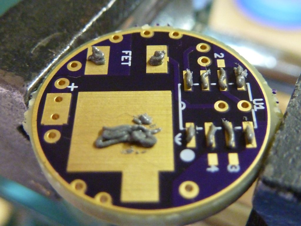
This is the placed parts on to the wet solder paste:
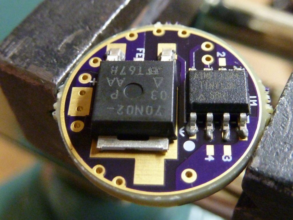
I use a hobbyist hot air gun which is low air speed, so pretty safe to do reflows. Takes like 30 secs to 1 minute but works well. After the reflow:
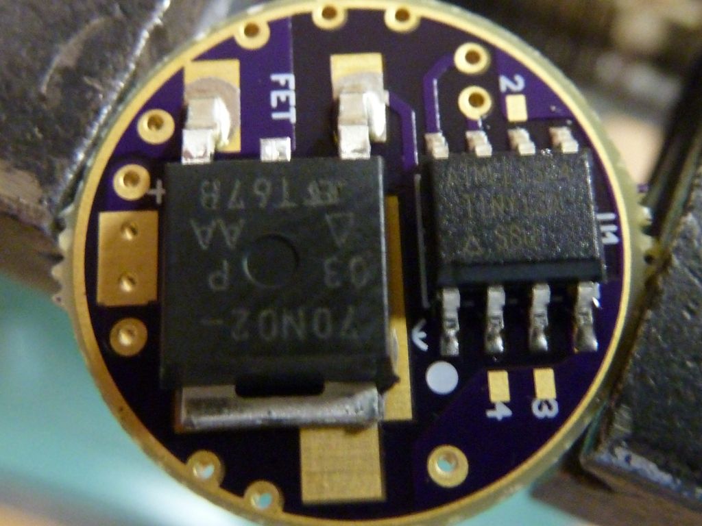
Again, this is showing parts position for the reflow. This sample is for a zener mod. Note the 200 ohm resistor (2000) is used in place of the diode:
This is after the reflow, and shows the Zener Diode soldered onto the side of the cap:
Detailed view of the diode. The marked end of the diode is on the opposite side from ground:

 .
.