Hello all,
[Update Jan 2021 - This driver has evolved to the Lume X1, check it out here! https://budgetlightforum.com/t/-/65319 ]
It's been a long while (half a year or so?) since I've been back to BLF, and I hope everyone is having a good start to 2018! Over the past some two weeks and a half a lot of things has happened so I'd thought I'd share some here. It all started from when I found some time to do a proper write-up for my GXB17 driver which you can read in detail on my webpage here.
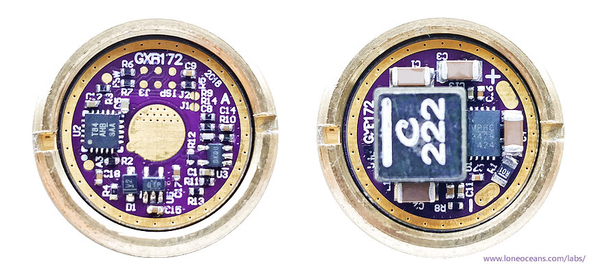
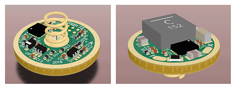
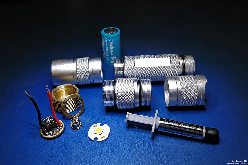
Above - the GXB172 in a brass Convoy S2+ Pill
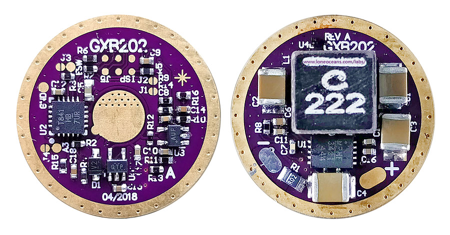
[New!] - Above, 20mm version, the GXB202 with larger passives and more edge clearances.
Summary
I'd like to share a little evolution of my previous drivers. I've called it the GXB172, and it's very similar to the GXB17 driver, but is capable of handling 50W! The driver has been tested to ~7.2V at 6.5A output so far. It's a little silly and not at all practical because any flashlight holding a 17mm driver would most likely not be able to sink all the heat and the light will throttle down hard really quickly, but it was still a fun project getting it to fit a 17mm form factor since it'd be really much easier (and more powerful) with discrete FETs for say a 30mm driver! It's getting pretty late here so I'll post this for now and write updates! Eventually I'll be writing up a detailed page with all my design details and source and schematics etc on the GXB172 page.
Project Status (End Mar 2018)
Currently the GXB172 is verified to be working. Basic functionality checks out. One driver has been installed into a Convoy S2+ for real-life testing. All basic firmware features appear to work as intended, except thermal throttling needs a bit more fine tuning. See the first GXB172 build here: https://budgetlightforum.com/t/-/50373. Driver has so far been tested with XHP50B at 6+A, Nichia 144 at 4.5A, and XHP35 HI at 2.5A (14.7V) (new).
Feature List
Here are some of the general features, many more to come with more work to be done on the firmware. In no particular order:
- Input - Nominally 1S (e.g. single 18650), ~2.7V to ~4.4+V, But works with 2S as well if the right Vreg/LDO is used (and firmware written to take advantage of this)
- My guess is that if the flashlight can hold 2S, it should be big enough for a bigger driver :P
- If you're thinking about something like a 2S 18350, my thinking is, why not just go for a single 18650? In the past a 2S might have been used for a non-boost driver, but this driver helps to overcome that gap :)
- Output 6V - Tested up to 7.24V at 6.5A, around 5mA for moon-light mode with a Cree XHP50B
- Output 12V - Tested up to 14.7V at 2.5A, and around 2-3mA for moon-light mode with Cree XHP35HI
- True Constant Current control, no PWM flickering, 1024 linearly-spaced brightness levels
- 17mm Diameter, 4 Layer PCB
- Attiny841 programmable microcontroller
- Ultrasonic switching - never drops below 23kHz so no high-pitched whine even at moonlight mode
- Candle-mode - just for fun, but simulates a flickering candle (working on simple algorithm to make it 'look right')
- Accurate digital temperature sensing with digital temperature sensor
- Much more accurate and and consistent than NTC or thermistor
- PID temperature regulation - automatically varies output on high modes to maintain set temperature
- Battery Voltage Sensing (for 1S and 2S) and low battery cut-off etc
- E-switch support (e.g. can work with Narsil with some tweaks, firmware work required)
- 3x additional GPIO
- 2x jumpers / 1x pads(e.g. can be used to say configure for up to 8 different modes without firmware change)
- Alternatively can also be used to drive extra LEDs for indication lights, button backlighting, buzzer etc
- EEPROM Memory
- Firmware Support (in progress)
- With a suitable host, I'm very sure I with a little bit of work, this will work just fine with a modified Narsil E-Switch firmware
- Likewise with Biscotti / Bistro, this can work as well since this driver has hooks and hardware for both OTC and OTSM
- However, there are some non-trivial modifications needed to work with this driver due to many aspects, so I've made my own simple firmware for now (more discussion later)
- Efficiency >90%+ for most output levels, over 95% at 1A output.
Background
As you may know, my GXB17 and GXB20 project started when I wanted to make a really bright (2000 lumen) but small flashlight powered by a single 18650 battery. Back when I started the GXB20 project, I don't quite recall if there were any affordable single-cell XHP50 lights around. So this changed I was discussing the GXB projects with a friend, and found that he recently bought a new Zebralight SC600Wiv+, which is a small single-cell light which also does 2000 lumens from a single XHP50!
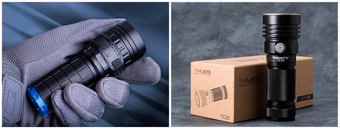
Not only that, I was also told that there were some new ~3800 lumen single-cell (albeit 26650) lights around which were all just released late 2017 (while I was away)! Specifically, these were the Imalent DN70 and the Thrunight TC20. My thoughts started from "how could this be!!??", and quickly turned to "how can I improve on the GXB drivers to achieve the same output..?".
Granted these two (and I'm sure there are more now on the market) flashlights used a very high power XHP70 LED. But I recall that Texas_Ace and Djozz did some tests previously on XHP50 LEDs and found that if driven to a pretty ridiculous 6A or so, one could achieve close to 4000 lumens! With this, I had a new goal - make a ridiculous driver capable of driving a XHP50 LED to 4000 lumens in the same 17mm driver size. I could use a XHP70 but I really wanted to keep the theme of a ridiculous driver (because such a small host with such a large drive power is thermally limited a few tens of seconds of operation), and use the same Convoy S2+ or similar 17mm flashlights for my new build (where I don't think the XHP50 would physically fit inside the reflector).
So this was the start of the GXB172.
Design and Operation
My GXB17 and GXB20 drivers both used a fairly decent boost converter IC, in fact, the most powerful fully integrated one which I could buy on the market, the TPS61088. However, in order to drive an LED at 6A, it will need something like a V_fwd of 7V (42W output), or about 50W input. From a single cell, (expecting voltage drop to say 3.5V), I'd need something capable of ~15A or so. But the TPS61088 is only good for 10A, or close to 12A peak. How to drive it without resorting to external FETs and a multi-board construction?
As all hobby EEs do, the first thing I did was to do was to do a quick parametric search to see what options were on the market, and behold! I found some new components which I had not seen before just half a year ago! Previously the TPS61088 was the high at 11.9A! This new Boost IC turned out to be the Monolithic Power Systems MP3429/3431, both essentially identical except the xx31 having an adjustable current limit. This looks like it'll fit the bill!
[More to come - I'll continue updating this page later!]
Driver Development
The moment I found the new IC I was pretty excited and I literally spent a weekend afternoon creating a super simple schematic and rushed off a dev-board PCB to be made!
I knew that I wanted to incorporate some fun new features which I thought of only after developing my GXB17 and GXB20 drivers, and I figured that a simple 'dev board' would allow me to (1) much more easily probe the board and (2) allow much easier firmware development. For control system, I had previously taken apart a H1-A 22mm boost driver and I decided that the control system was better since it used fewer components, so I have adapted it with changes. Essentially the control takes a low-side voltage measurement from a sense resistor, and compares it with an analog voltage generated via PWM from the microcontroller. For this to work, a good quality low-input-offset Op Amp is needed. In addition, the last time a few people suggested to me to use an ATtiny841, but at the same time I also wanted to try other MCU options, so I also added hooks for soldering on a second MCU (the Atmel Attiny1616 is an interesting candidate since it's one of the new ones after the Microchip acquisition), but for now I've gone with the Attiny841 which is much more capable than the Attiny85 or 84A.
As you can see the dev board allows me to connect a whole bunch of probes to it, my AVR ISP programmer, as well as input and out via screw terminals, debugging LEDs, an E-Switch for E-Switch development, and two footprints for different MCU options if desired.
With the design optimized after tinkering around with the dev platform, I then designed the PCB and sent it off for fabrication!
 (slightly older version)
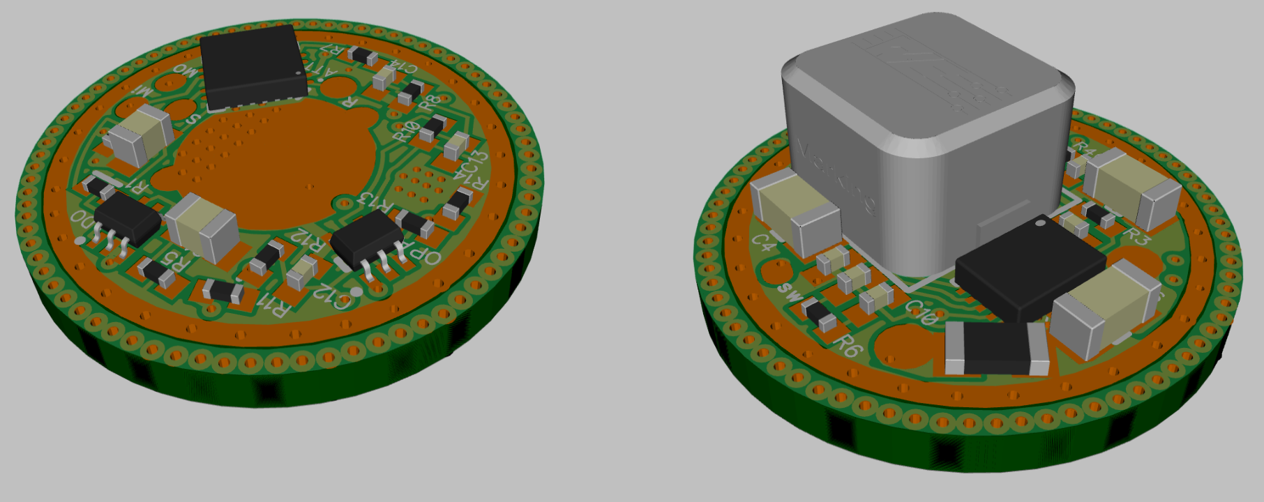
This time I decided to save myself some trouble routing in 2 layers, and went with a 4-layer stackup, since I realized that the cost for the PCB really is marginal since the PCBs are so small. This made routing very easy and it was done much faster than my previous layouts, and many fab houses including OshPark are readily available to anyone who wants to make their own.
 (current Rev A version)
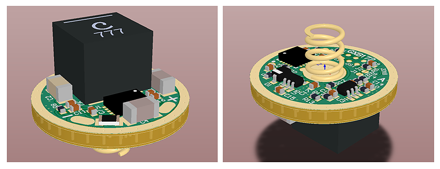
Above is an updated version of the layout which I sent to fab, and to show a comparison of what swapping out the inductor for a bigger one looks like. The big inductor will have better performance at the downside of increased costs and obviously, size! It may not fit many pills due to the height of the inductor. This is Rev A of the driver and I'm sure there will be a Rev B!
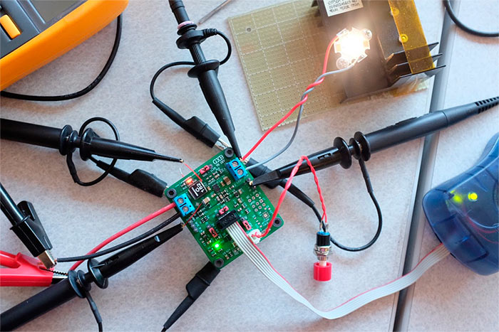
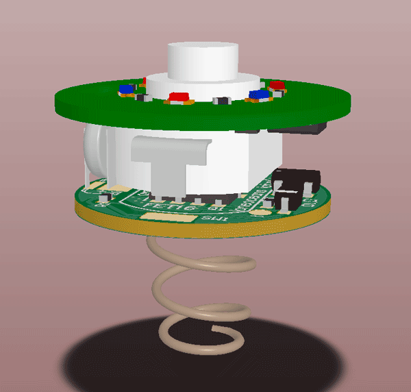
The PCB was received from the fab and soldered up as shown in the first image at the top of this post!
Firmware
Currently the firmware is a simple, basic one. There are some specifics which need to be done to ensure the GXB172 works properly so it's not a naïve port of Bistro or Narsil to make it work, but this will be done in the future. Meanwhile, I hope this charge gives a good idea of what the driver's existing functionality is.
Results
So it turns out that just after I visited this forum again and updated my old GXB17 thread, Agro informed me that Schoki had already started a 17mm boost driver with the same boost IC as well! Unfortunately I had already sent the PCBs to be made so I guess I really should have visited this page earlier and saved myself all this trouble >.<.... doh!
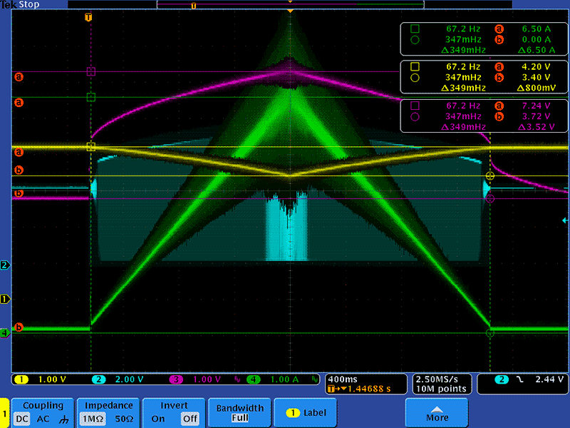
Anyway I was able to take some measurements! In this test, I wrote a very simple test program which ramps up the LED current from 0 to 6.5A.
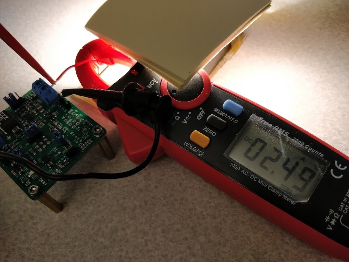
Above you can see the input voltage in yellow from a LG HG2 lithium battery (excuse the voltage drop, my battery cables were fairly long!.. and I had to use a battery since I had maxed out the 8A of my power supply!), the output voltage (magenta), the output current (green) and the switch node (cyan). The driver was hooked up to a XHP50A LED on a copper MCPCB and clamped onto a heat-sink (same as the one in the photo above).
Looking at the peak of the current drive, the GXB172 has an output of some 7.24V at 6.5A (47.06W)! This was at an input voltage of 3.4V and about 15.6A on the input (clamp meter) for a total efficiency of around 89% (much higher at more 'reasonable' drive levels!). This is about as high as one can go without increasing inductor size (e.g. going up from the Coilcraft XAL7030 to say the XAL7070 but those look pretty ridiculous!) and dropping the ripple current, since we want to have some headroom above the inductor and switch peak current! So far it seems like the driver is not thermally limited per-se, i.e. the LED produces so much more heat that it'll end up heating the driver up more than the losses in the driver.
12V LED Configurations (Apr 2018)
GXB172 has been successfully tested with just about 37W output drive on a XHP35 HI LED. Measured LED current was 2.50A at 14.7V.
Work is also underway to develop a 20mm driver form-factor (GXB202).
First Build - Real Life Testing (in progress Mar 2018)
Currently the GXB172 is verified to be working. Basic functionality checks out. One driver has been installed into a Convoy S2+ for real-life testing. All basic firmware features appear to work as intended, except thermal throttling needs a bit more fine tuning. See the first GXB172 build here: https://budgetlightforum.com/t/-/50373.
Current the driver has been set up with a Nichia 144 6V LED driven to 4.2A.
I'm also toying with the idea of implementing this in E-Switch mode (e.g. with the Convoy S9), which will give us much better performance since we bypass the switch entirely, and it's also much safer on the electronics (15A+ interrupt current is not a good idea! But neither was making a 50W driver in the first place :P).
Meanwhile, in order to handle the massive current without too much voltage drop across the switch (can be as high as 0.5V or more at 15A even with a good switch!), I made a companion FET switch for 1-3 milli Ohm switch resistance.
Please see this thread for more information: https://budgetlightforum.com/t/-/50404.
Frequently Asked Questions
Many of the questions I've received are the same, so I thought I'll make a little FAQ section!
- Is this driver for real or are you making this up?
- It's not real, but actually working decently well! I'll be passing some drivers to forum members for testing soon, but meanwhile, check out this video of a preliminary GXB172 in action in a Convoy S2+.
https://www.youtube.com/watch?v=M-_C1XHUgQw
- It's not real, but actually working decently well! I'll be passing some drivers to forum members for testing soon, but meanwhile, check out this video of a preliminary GXB172 in action in a Convoy S2+.
- What is the status of this project?
- Hardware seems to check out good. Basic firmware seems stable. Some tweaking needed for thermal control. However, still work needed to be done to port the popular Bistro / Narsil firmware over, which will take some time. However the driver as it is, is working!
- What firmware does this support?
- Currently the driver uses a Attiny841 MCU running my own firmware. It's similar to the BLF A6 firmware with a little less configuration features at the moment, but adds additional capabilities like candlelight mode, smooth ramps, PID temperature control etc. Eventually I hope to achieve parity with Bistro / Biscotti and Narsil, but that is going to take a while since it's not a simple MCU change, but rather it needs to handle a bunch of differences unique to the GXB172, which are not present in the standard 7135+Fet combination
- Are you offering these for sale?
- Not yet! I don't plan to make any money from this since it's just a personal fun project. However it seems like a lot of people are interested. Yet I do not want to release a product for sale which is not 100% solid. That said, regardless of how long it takes to get to a solid state, anyone will be free to make their own driver at their own time if you want to! :
- Will there be 20mm version?
- Yes! Because I have some SK98 hosts to upgrade from my GXB20 driver. In fact, going up to the 20mm size allows me to add even more cool features and better layout to the driver, i.e. it won't just be a copy paste of the GXB172. Stay tuned!
- Will there be >20mm versions?
- Not sure, but currently I have no plans for >20mm versions. The reason? If you want to go higher, there are far better options than the architecture as designed in the GXB172, e.g. you can use discrete external FET switching solutions since space is no longer a constraint. The uniqueness of the GXB172 and 202 are its small size. Sure I could easily make the same layout on a larger PCB, but that seems contrary to the original ethos of the GXB series of drivers. :) Anyway we'll see how that goes when we have a successful GXB172 and 202 first.
- Will this work with a regular tail switch?
- Of course! However you may encounter problems if your driver is configured for max drive. For example, suppose you're pulling say 12A from the battery, and your battery voltage drops to say 3.5V. You have a switch with resistance of 30mR. The total additional voltage drop across is 0.36V, so the driver only sees 3.14V. This may cause the driver to want to draw more current to maintain output power, and current increases. Eventually you will hit the current limit or the driver voltage drops too low, and the driver falls out of regulation. As a result, performance is not guaranteed unless you know what you are doing, since the driver is capable of pushing a lot of amps.
- Will this work with 2S configuration?
- The hardware supports this, IF you are trying to use this to drive a 12V LED. However a little bit of firmware needs to be done to handle the higher voltage to make sure the battery sensing is accurate, and some resistor values may need to be tweaked. But otherwise there's no reason why it won't work.
- Will you be releasing the design, BOM, schematic, etc?
- Don't worry, this project is not for private use - it's meant to be public and free! As with my older projects, I'll be releasing all of them for free under the creative commons with hopefully useful documentation. I'm still working on the design but it'll all be up on my website available for you to make your own and/or make improvements if you wish!
- Is there a place I can get the PCBs from for now?
- Yes you can order your own GXB172 Rev A PCB on OSHPark yourself right now here, but more details to come..
- How about the firmware?
- Same thing with the firmware! :)
- I want to assemble this myself, is it possible?
- Yes, but I highly recommend having access to some sort of magnification (EE microscope or magnification camera), a small soldering iron tip with very thin solder and needle-nose tweezers, as well as a reflow oven if possible. All my prototypes are assembled at home, so you can do it too with some experience!
- Yes, but I highly recommend having access to some sort of magnification (EE microscope or magnification camera), a small soldering iron tip with very thin solder and needle-nose tweezers, as well as a reflow oven if possible. All my prototypes are assembled at home, so you can do it too with some experience!
- How long does the light stay in turbo before throttling?
- At 50W, from a ~20C starting temperature, it takes less than 30s for a Convoy S2+ to heat up to more than 60C at the pill, where thermal throttling begins. You can either increase the thermal limit from 60C to higher, or use a better host with better cooling.
- Doesn't this mean this driver is useless?
- At turbo I suppose! But that's the point of the GXB series - to make a ridiculous driver! To be fair, the Emisor D4 also runs at turbo for just about half a minute before also throttling down. Also keep in mind that with PID control, as long as you keep the light cool, it will maintain maximum output for as long as the batteries can sustain, even when it has throttled down (e.g. you dunk it in snow after it starts throttling, and the light will go back up to full output). In addition, you can also adjust the modes yourself to set the max to a more reasonable 10W, then it works just fine as a normal everyday driver, but with the added bonus of being able to use some beautiful 6V or 12V emitters, via a single cell
- What hosts does the GXB172 fit into?
- The base diameter of the GXB172 is 17mm, so any host which holds 17mm should allow the driver to fit. However, the main size constraint is the large inductor on board. For best performance, the 7mm tall inductor should be used. A smaller 3mm can also be use, but at the cost of reduced performance and regulation, and reduced efficiency. If possible, the larger inductor should always be used if space allows. I know this driver fits perfectly in a Convoy S2+, but I have no other flashlights to test otherwise, so YMMV!
Hopefully this will be a driver which people will find useful. 
Thanks for reading and I'll continue to post updates as this project progresses.