how it began can be read here
each generation adds more features
Generation 1 is now available for D4, High/low capability but then LEDs dim to about 50% between full and empty battery
LVP can be added for 0.7€
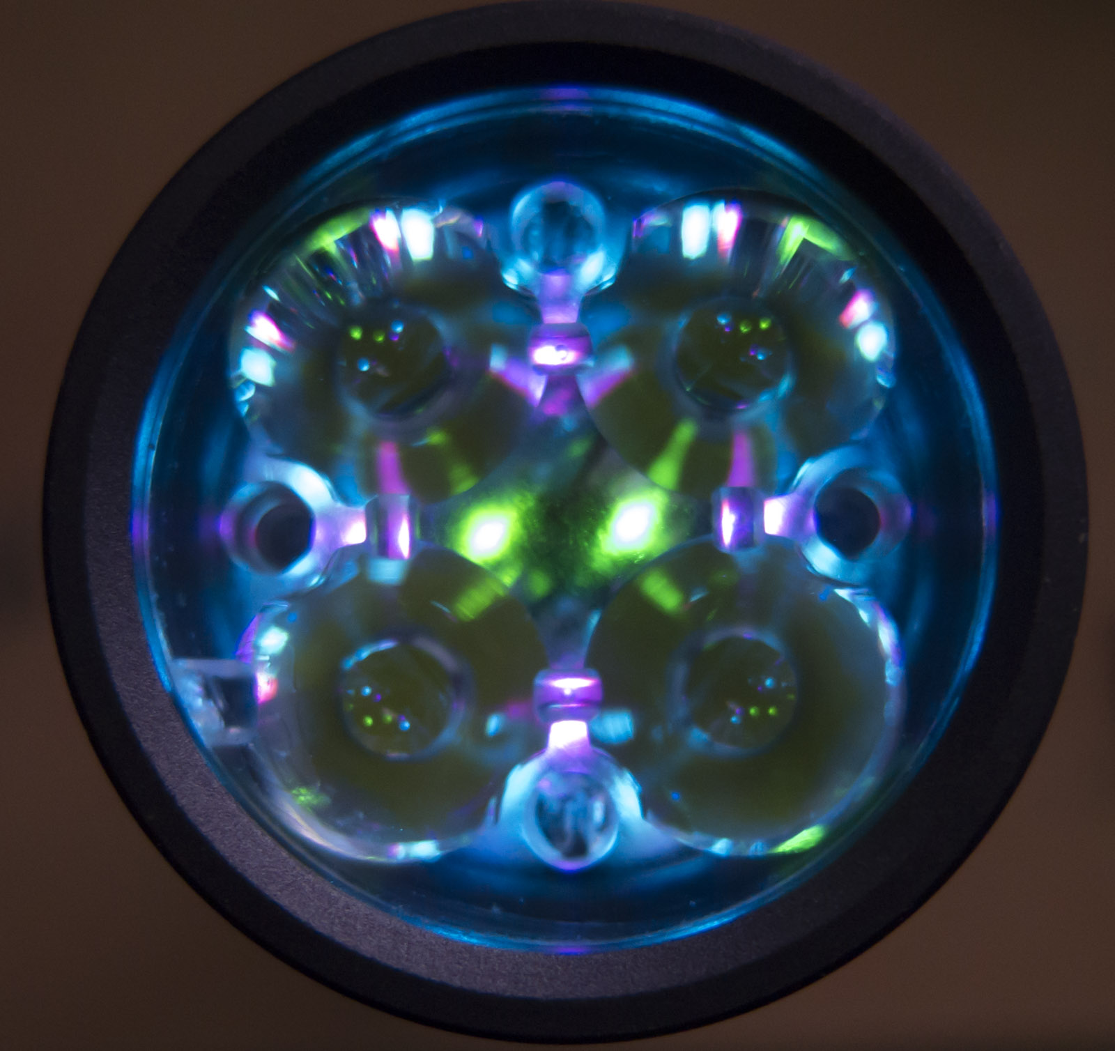
Generation 2 2 groups of LEDs or rainbow added voltage stabilisation
2.8V 18uA LDO used to keep brightness stable down to about 3V battery voltage
trimmer optional
Generation 3 2 groups and low battery LED (s) added low battery warning and LVP
lights up with constant brightness
low battery: 2 groups get switched off and red LED turns on to indicate low battery
LVP: at 3V all LEDs are switched off 2.8V LDO and IC standby current of 40uA remain
low battery and LVP can be set to custom voltages above 3V
Generation 3.1 added set of full battery indication LEDs
LVP now shuts down everything, reducing standby drain in LVP to almost nothing

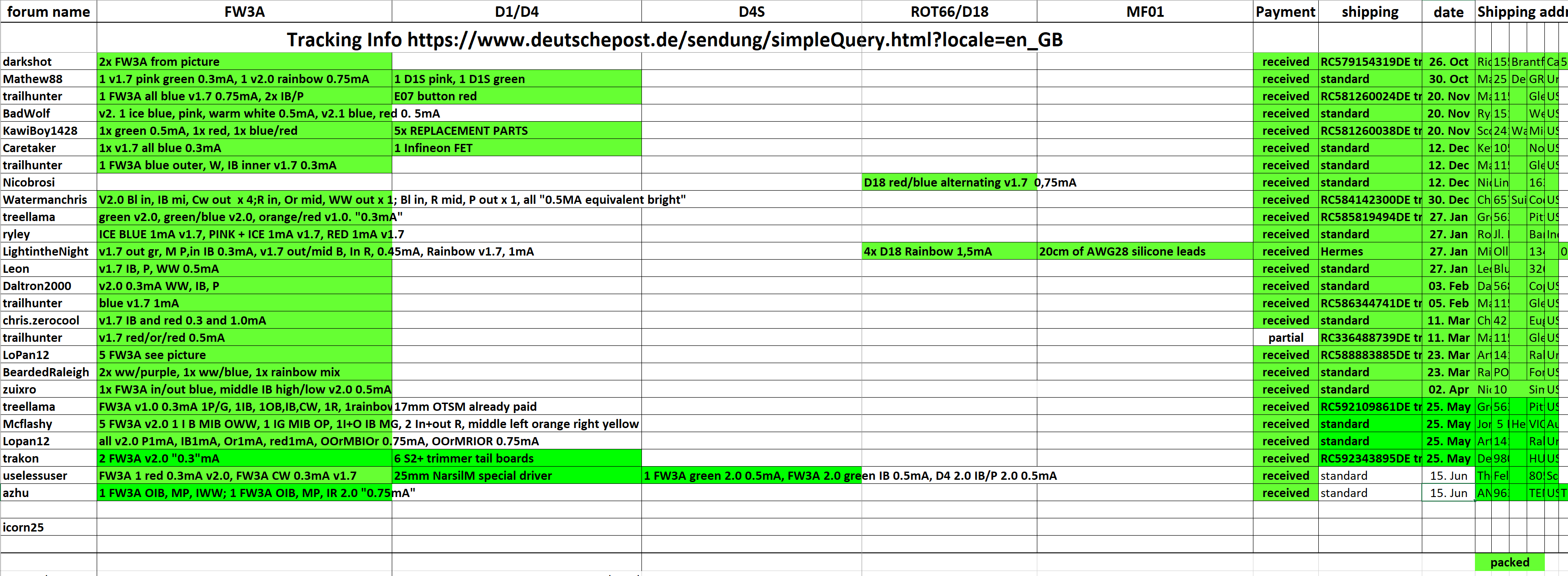
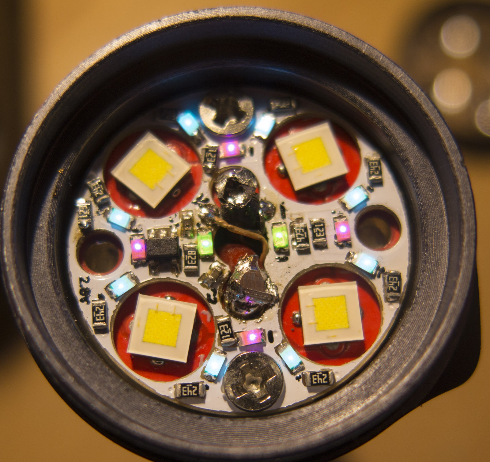
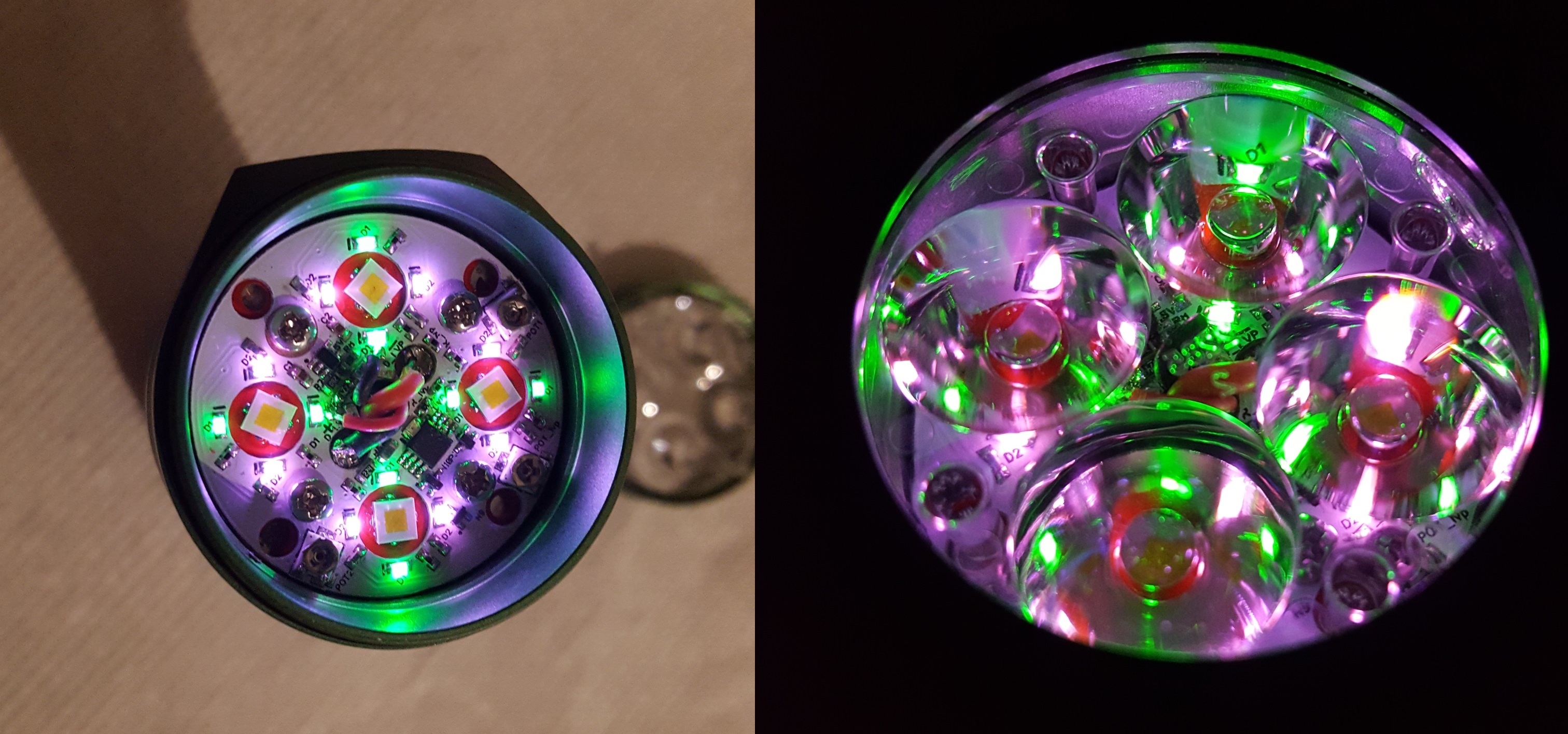
any color combinations are possible each LED could have a different color
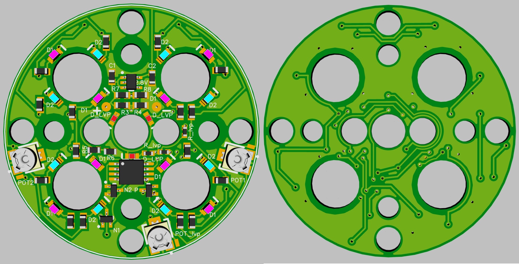
D4 based on genetration 2 tail light boards
D4S based on generation 3
Low Battery color switchand LVP shutdown
D4 Gen 2.1 (combines Gen 1 and Gen 2) with optional LVP
D4S 33mm 3 seperate trimmers to adjust inner and outer LEDs
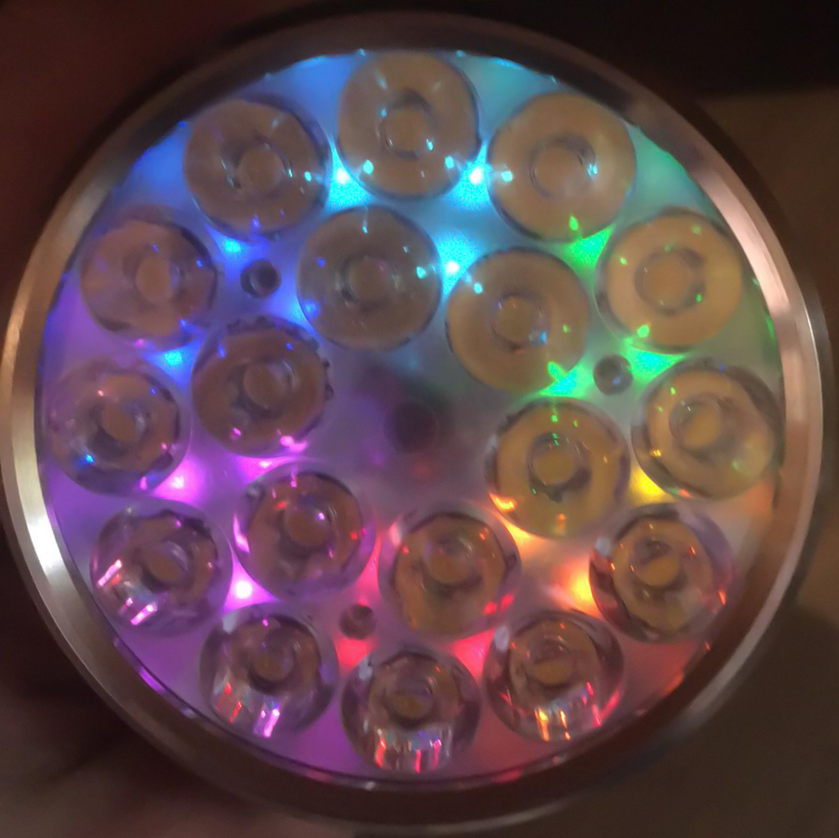
prototype D4S in pink/green
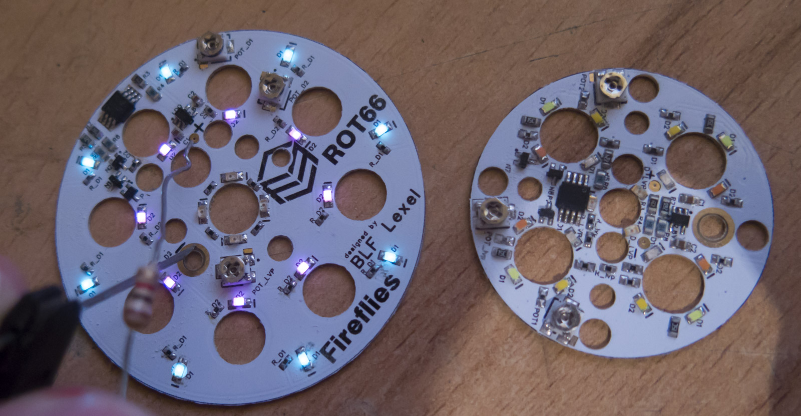
ROT66 next to D4S
MF01

LEDs as you wish colors and patterns
450nm blue, pink, red, orange, yellow, green, ice blue, WW, CW (the yellowisch green is too inefficient)
new LED batch comparator boards for 3 brightness levels made
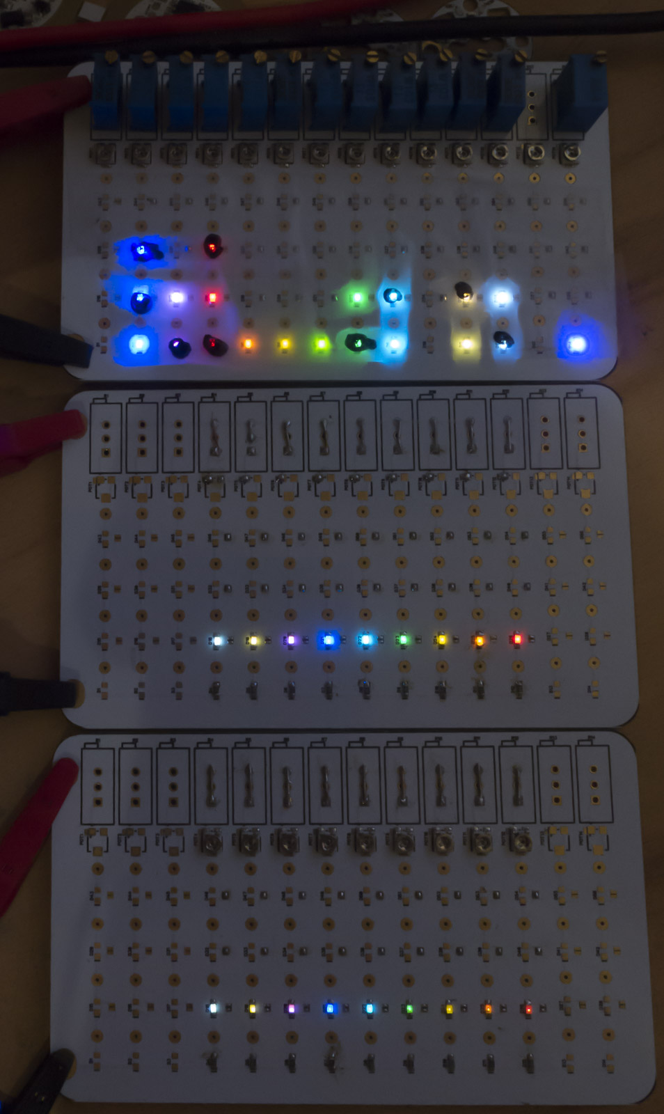
[LED colors] (top are most efficient, bottom inefficient)
LED color and each single LED current based on my “medium 0.5mA” brightness level
green 19.1uA
blue 21.2uA
ice blue 25.2uA
pink 30.7uA
CW 38.7uA
WW 40.2uA
red 50.9uA
orange 124uA
yellow 206uA
my LED brightness scale is based on my Rainbow+WW boards total current while LEDs seem same brightness
basically I have 5 levels “1mA”, “0.75mA”, “0.5mA”, “0.3mA” and “0.15mA”
this does only reflect on rainbow boards with WW the total current drawn
on the boards the total current depends on used colors and brightness level (“0.15-1mA”)
for example you order a “0.3mA” pink/green Emisar D4 all 14 LEDs equipped
total current 250uA
now we add 20k trimmers for brightness adjustment
total current at min trimmer level 100uA
It is possible to define a total current consumtion with trimmers on max position
I got a very complex table to calculate the needed resistances