Update 10/04/14: some highlights found in this thread:
- Post #96 is ROD911's impressions of a simple emitter swap to MT-G2 using stock driver, stock amps (post #114 is beamshots I can't view?)
- Post #118 - some useful info on resistors
- Post #126 - R100 result with a MT-G2, UCLp lens
- Post #144 - details on DMM wire leads used to measure amps
- Post #145 - aoeu's impressions/results on MT-G2, and grinding down the head (pic posted at post #184)
- Post #166 - details on the MaxToch 26 MCPCB used in a Y3
- Post #169 - fellfromtree's impressions, mods
- Post #262 - grantman232 posted some nice beamshots featuring 2 mod'ed Y3's - de-domed XM-L2 and a MT-G2
Just want to add grantman321 and aw73 seem to be having a similar issue of measuring only about 2.05A at the tail on one cell (should be 2.45 - 2.52A or so). My gut says it's the measurement methodology, but aw73 seems to be using proper leads on his DMM. Really dunno - could be a driver issue as wight pointed out, buck drivers are tricky on single cells. Not sure if anyone else has similar experiences.
Update 9/27/14: Post #166 shows details on a Y3 mod using the new MaxToch 26 mm MCPCB
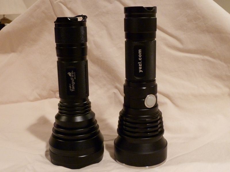
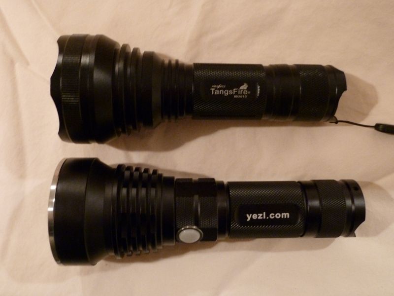
Following is a breakdown of the Yezl Y3 by pictures. Hope this answers some questions. First couple of pics are from a previous bought/sold Y3, most are new.
Shown with the classic HD2010:
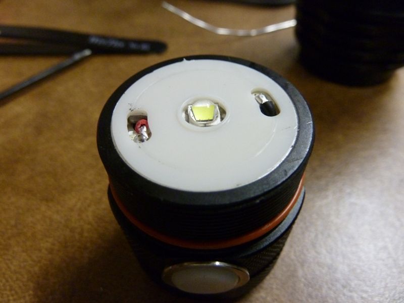
Tailcap:
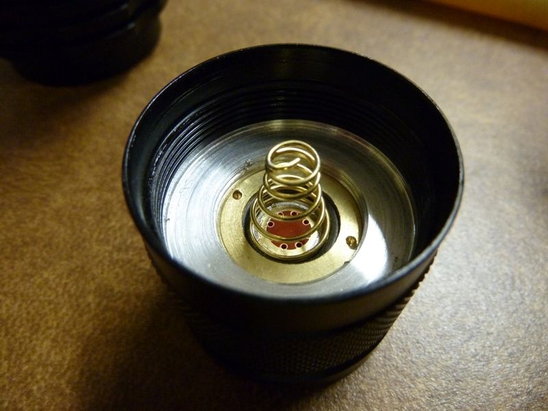
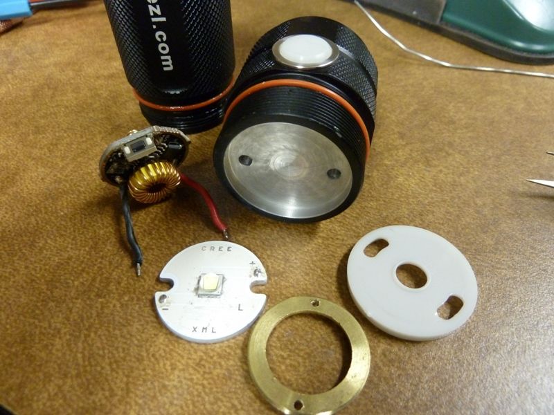
HD2010 on left, Y3 on right:
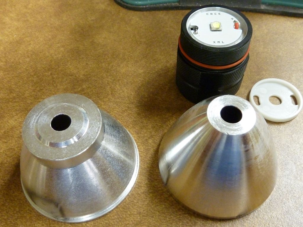
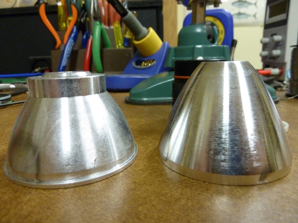
All my measurements were done more precisely than shown. I simply left the setting on the caliper and tried to show what I was measuring in the photo:
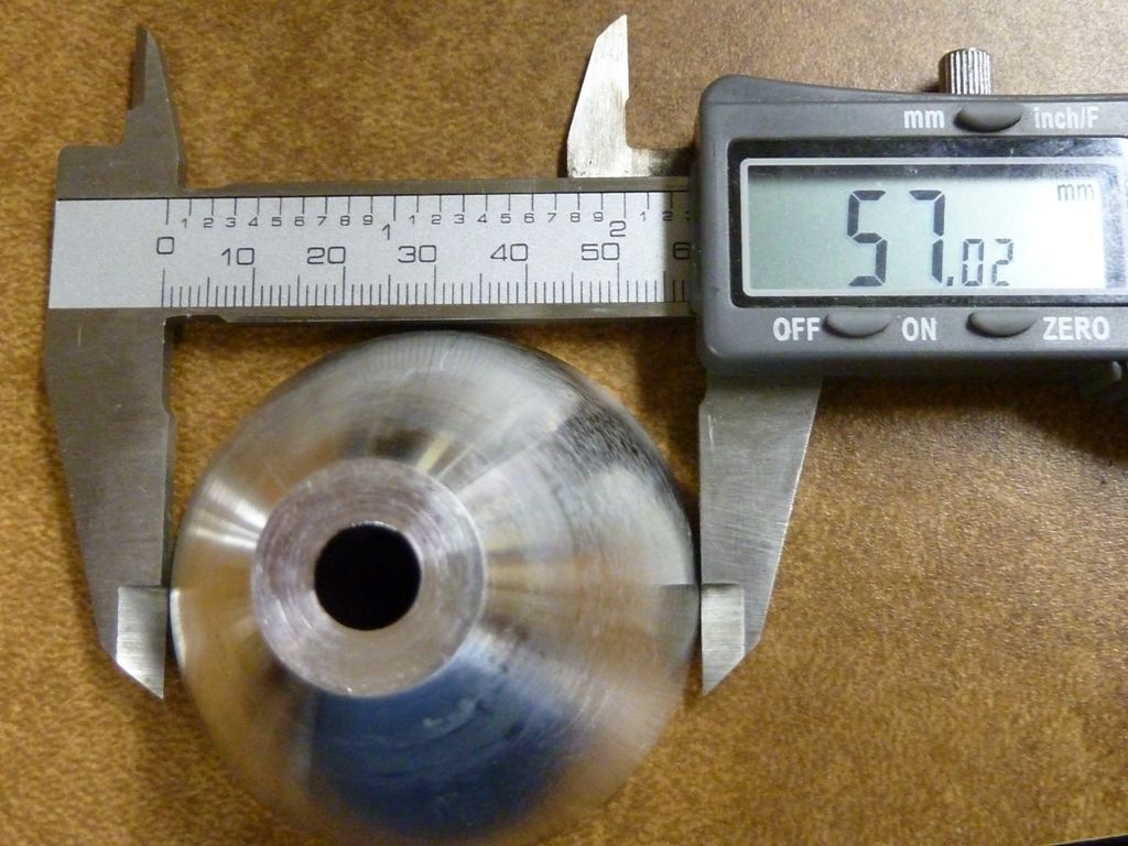
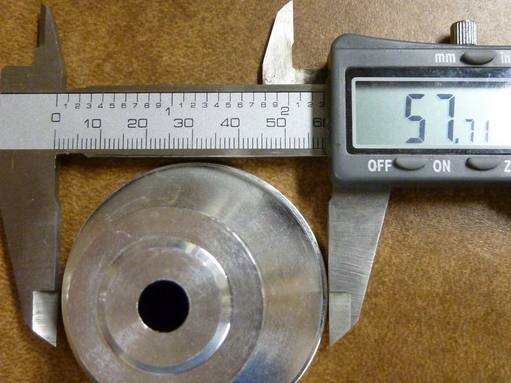
I.D. is what matters. Y3:
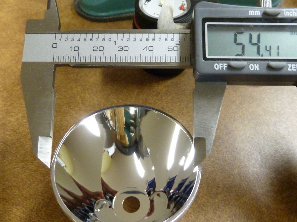
HD2010:
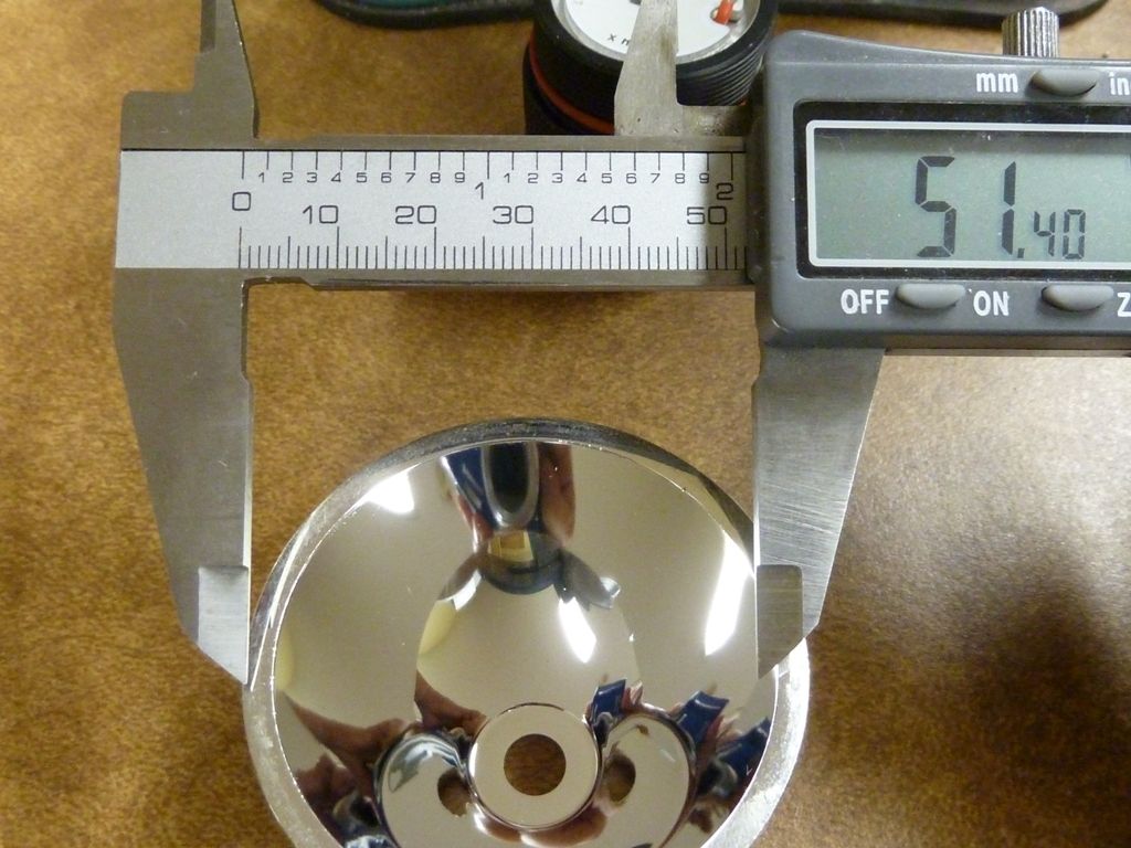
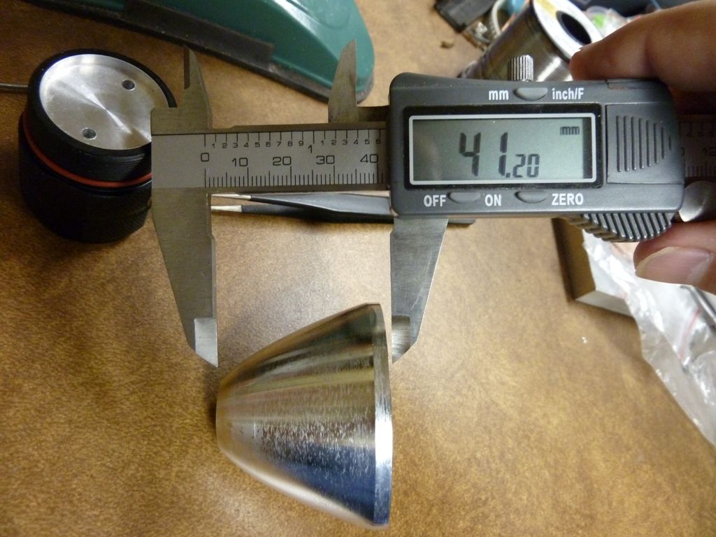
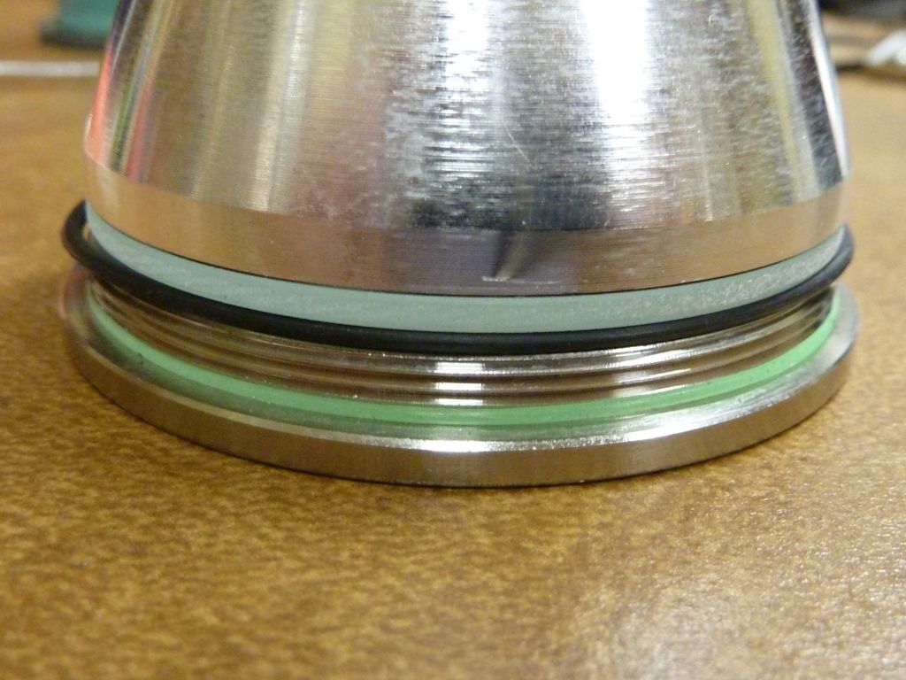
The front stack - the black o-ring is a little over sized, so you have to keep an eye on it wne re-assembling, that it doesn't squeeze out:
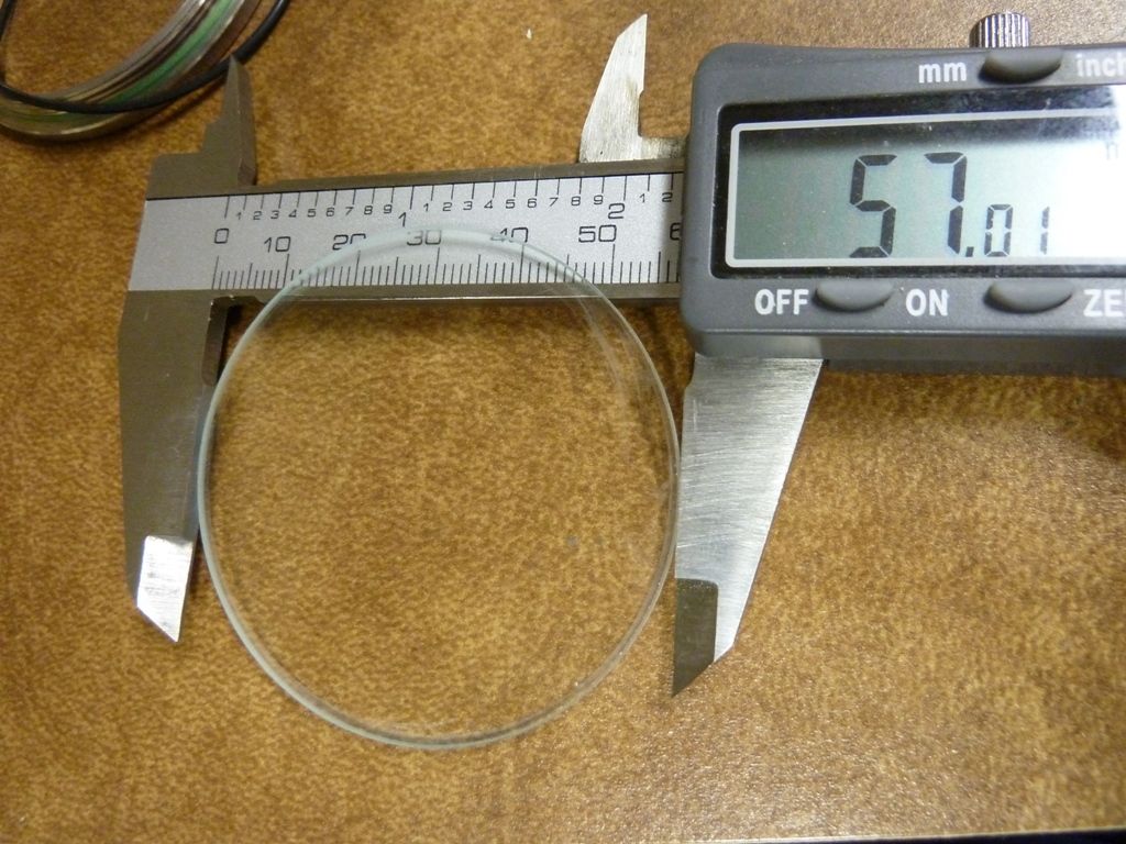
lens diameter:
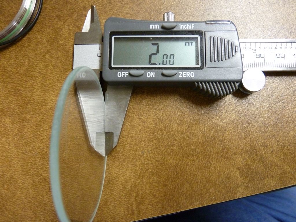
Thickness:
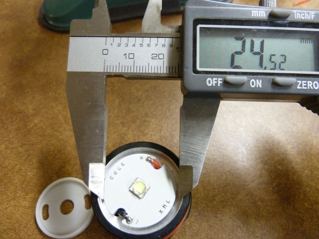
Diameter of stock MCPCB:
shelf width:
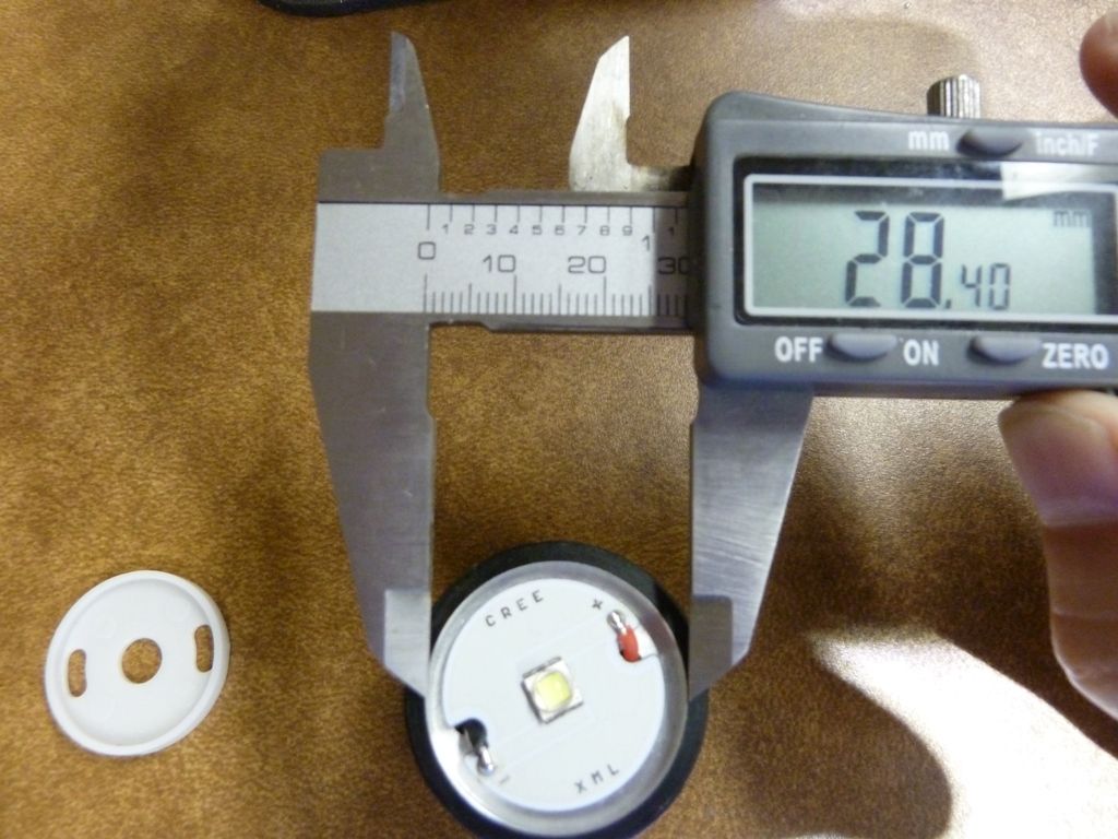
Dab of grease used, stock:
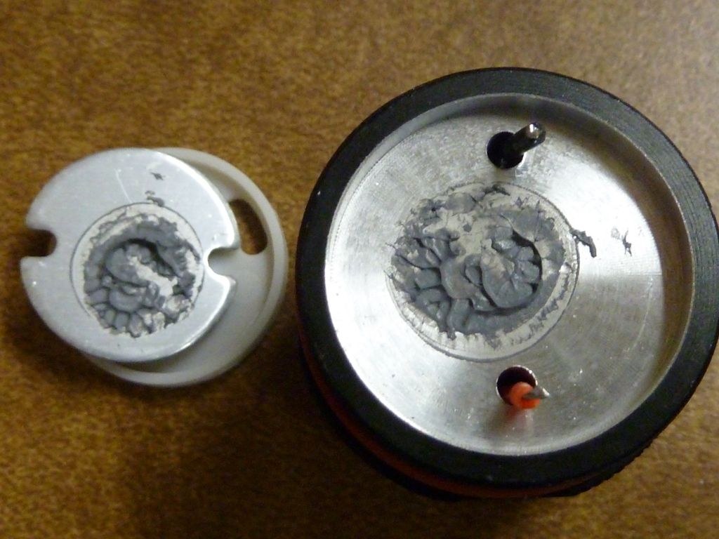
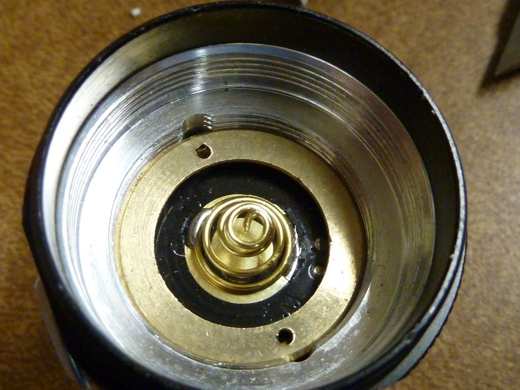
Driver, battery side:
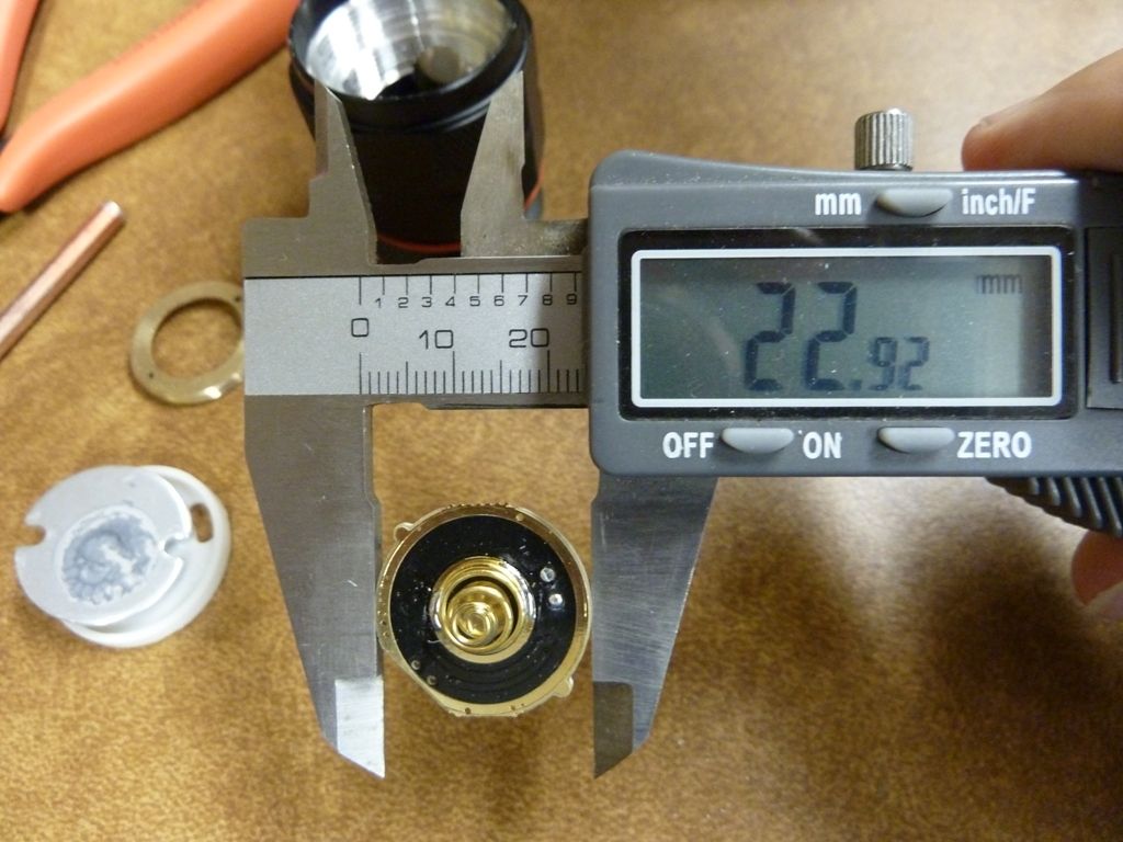
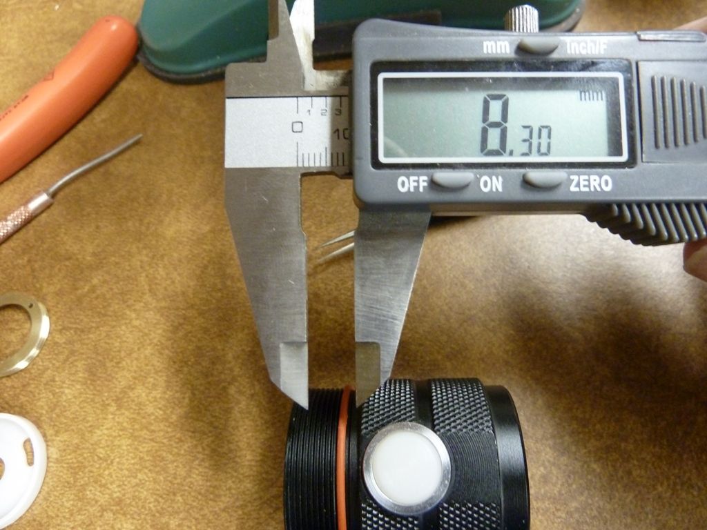
Driver diameter:
This is the shelf thickness (~). Measured at the LED wire holes using a tool, and marking where it's flush. It's nice and thick:
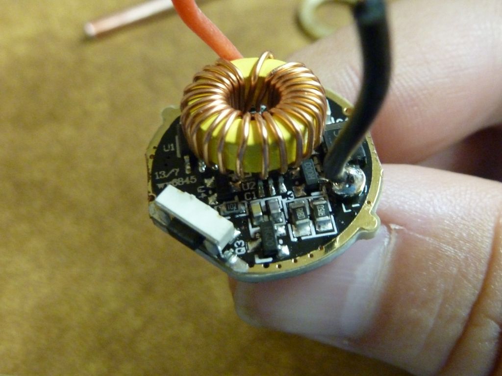
Stock driver:
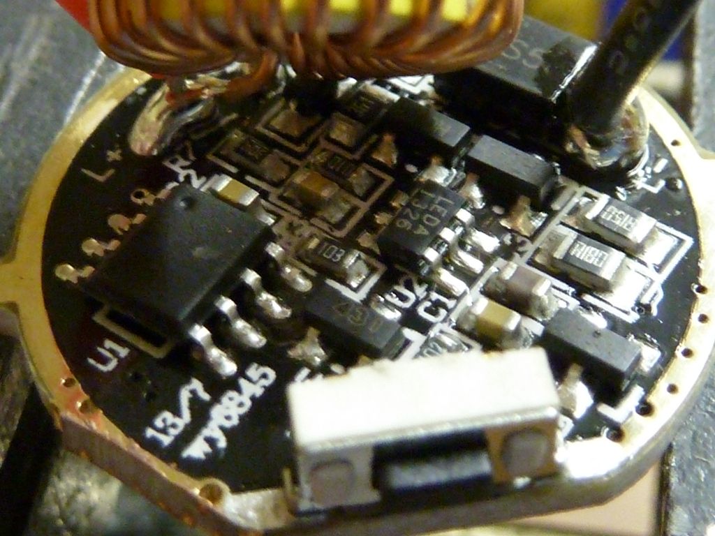
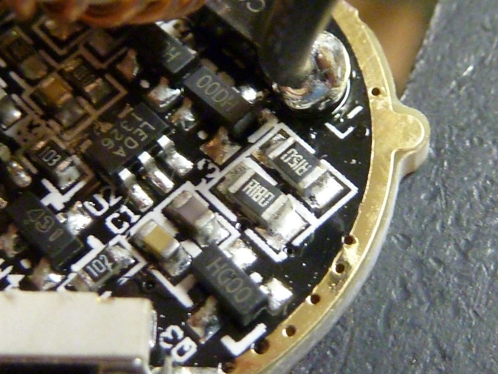
Nice smooth shelf top, but is it really flat as it looks?
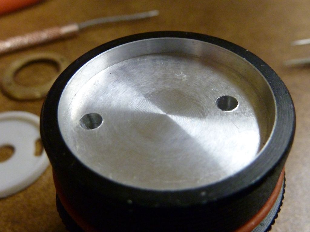
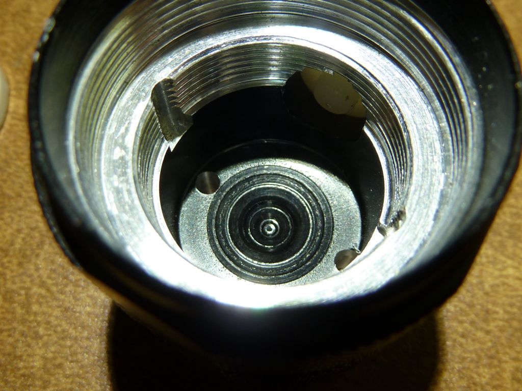
Inside of shelf top is not so flat - has an inny:
Tail assembly:
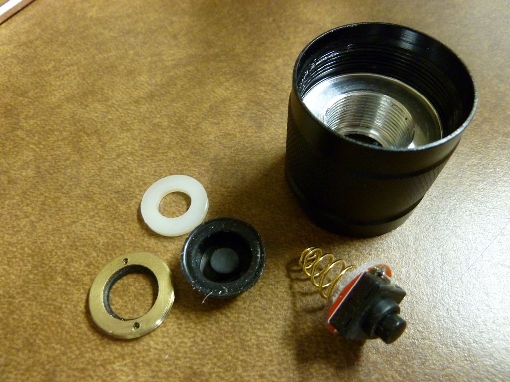
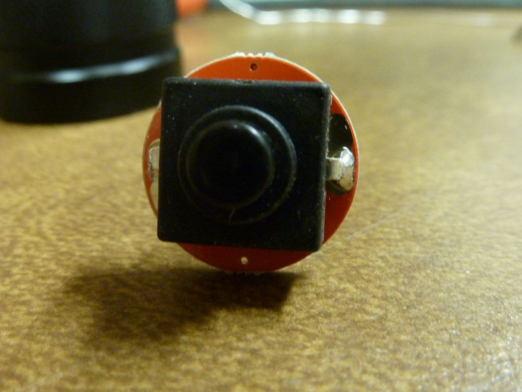
The switch is not typical rectangular, but looks more like a tactical (fwd) but really is a reverse clicky. It has not writing on it but appears to be good quality:
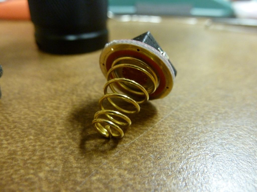
Ooops, maybe not so flat. I tried other flat surfaces besides this copper piece and all seem to indicate the same pattern. I also testes the copper piece on other flat surfaces and did not notice the unevenness as shown here. Hhmm - I did build a 5.7A Y3 before and didn't notice this, but I didn't look for it as I do now.
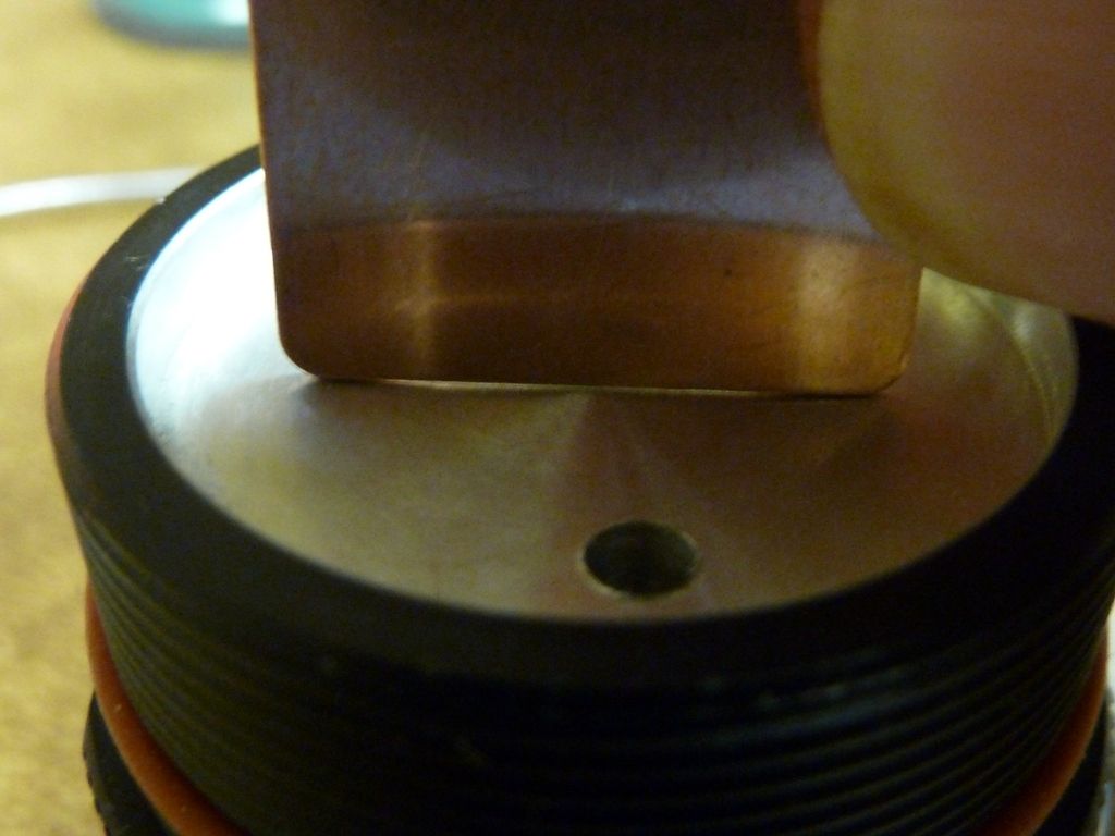
I can try sanding by hand, but don't think it will help much. If anyone has suggestions to get this flat, please post.
Update 08/03/2014:
Here it is after the sanding I did. Not much improvement:
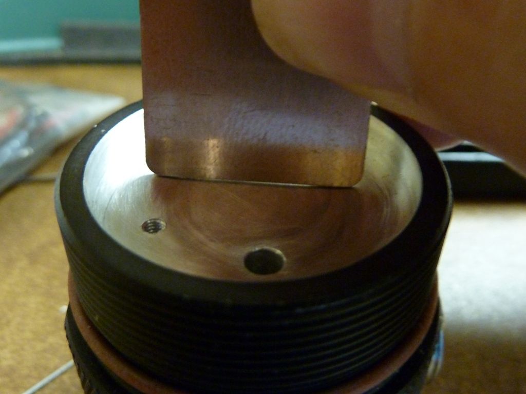
I used quite a bit of thermal grease and didn't see any squeeze out, so thinking there's still a significant gap.
Modding the Yezl Y3
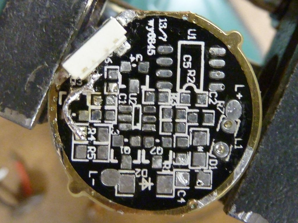
Stripped stock driver (hot air used, then cleaned up with solder wick and isop. alcohol):
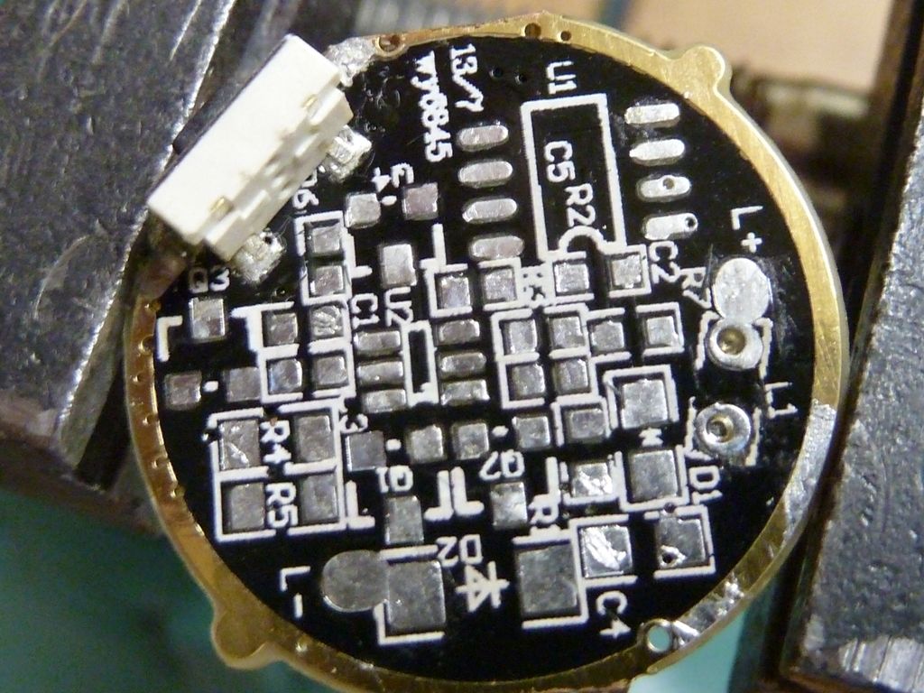
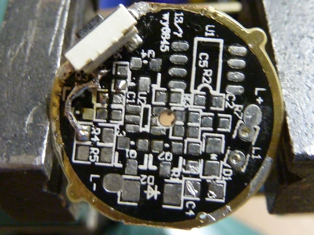
Added a jumper (upper left) to ground one end of the e-switch, and bring grounds to extra pads on the stripped board:
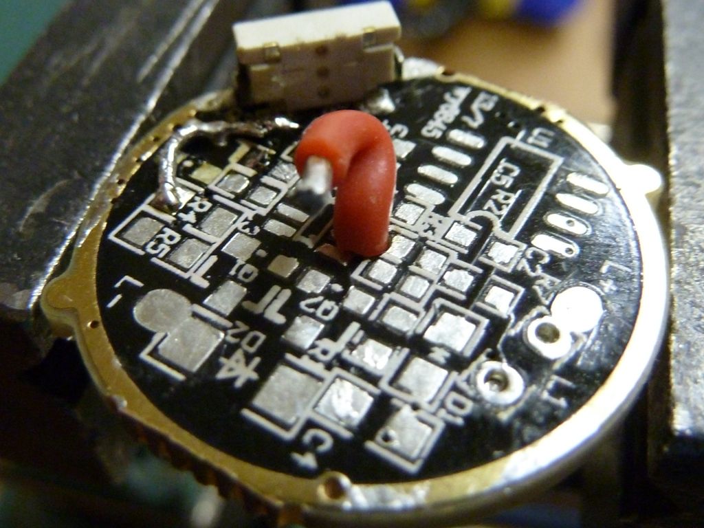
Drilled a hole through the PCB to route a + 20 AWG wire through (avoid small traces on the stock board):
Here's the wire in place:
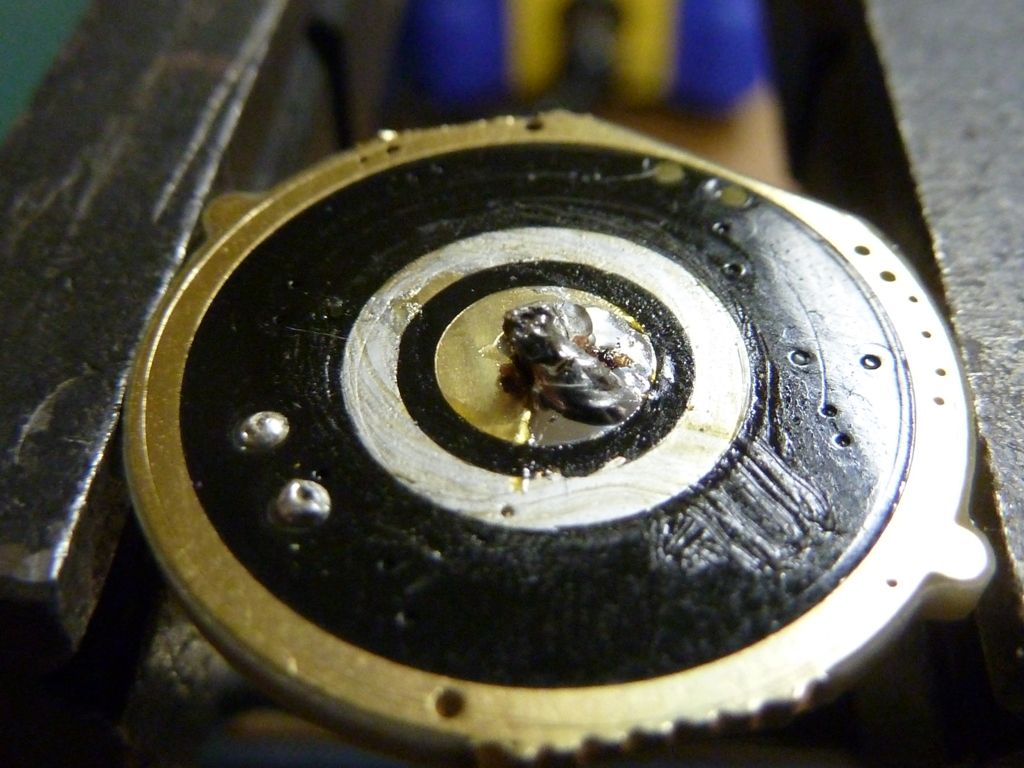
Soldered from below:
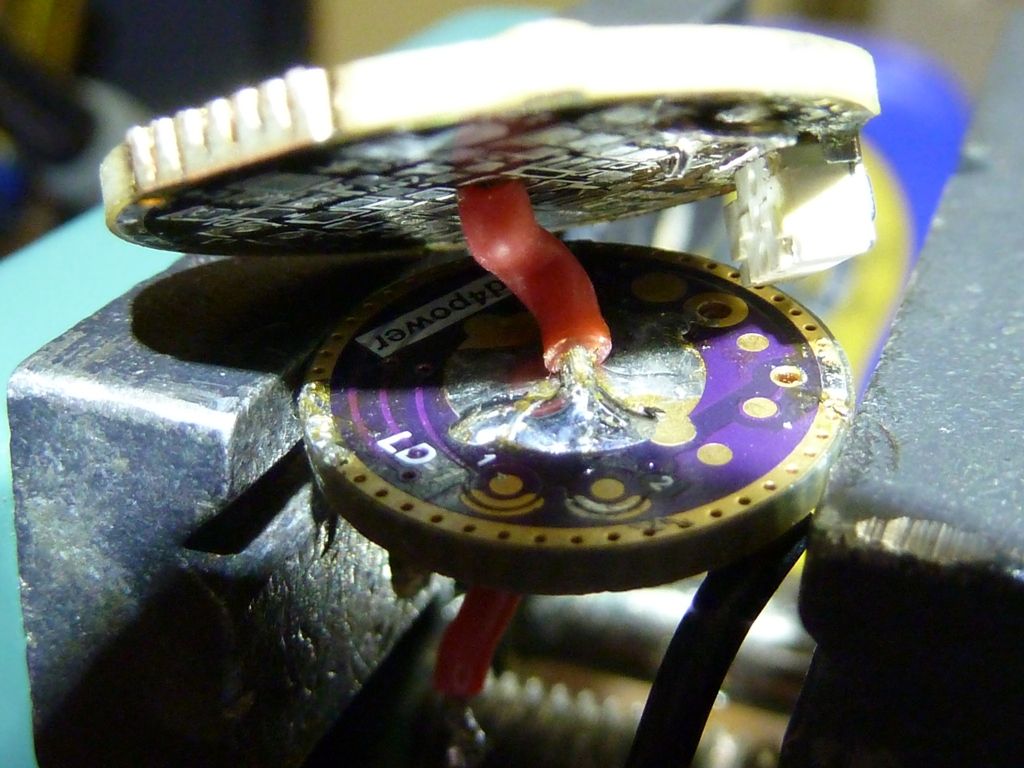
Soldered up to the LD-1:
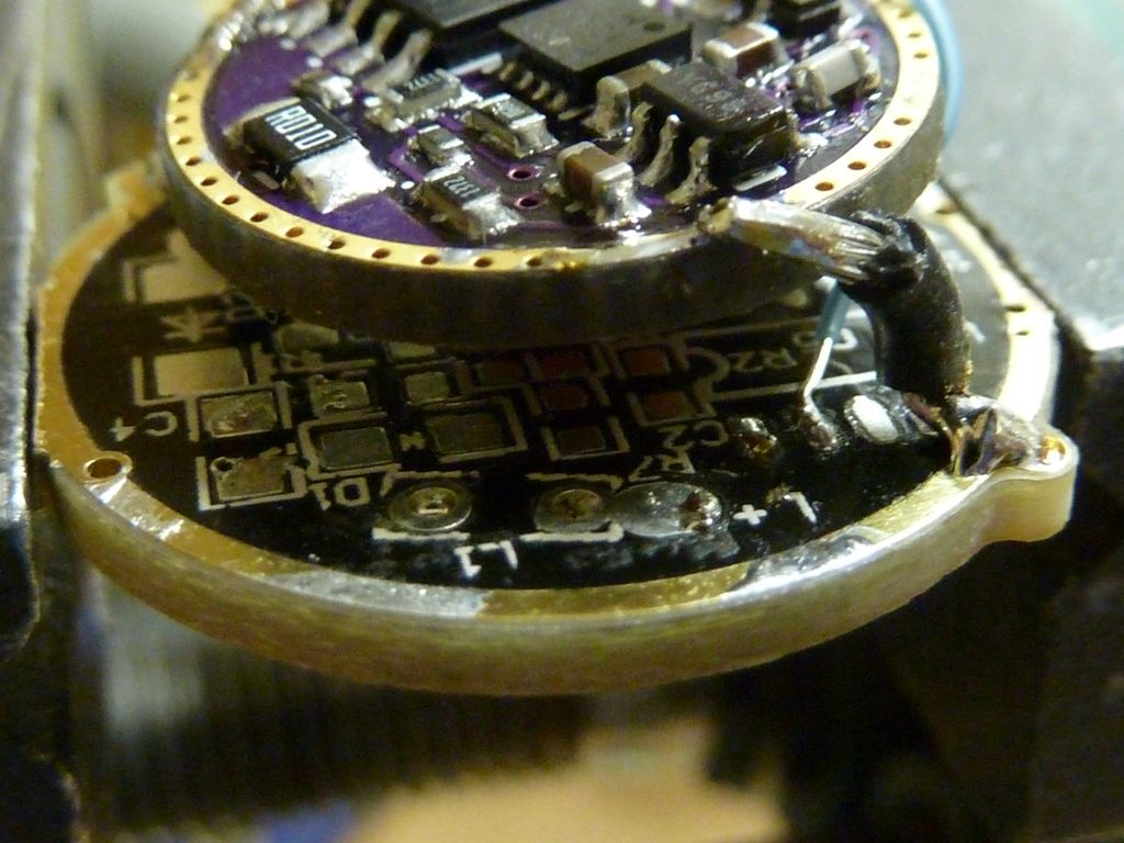
Two ground connections and the e-switch wire added from a MCU pad on the original stock driver to the e-switch input of the LD-1 driver:
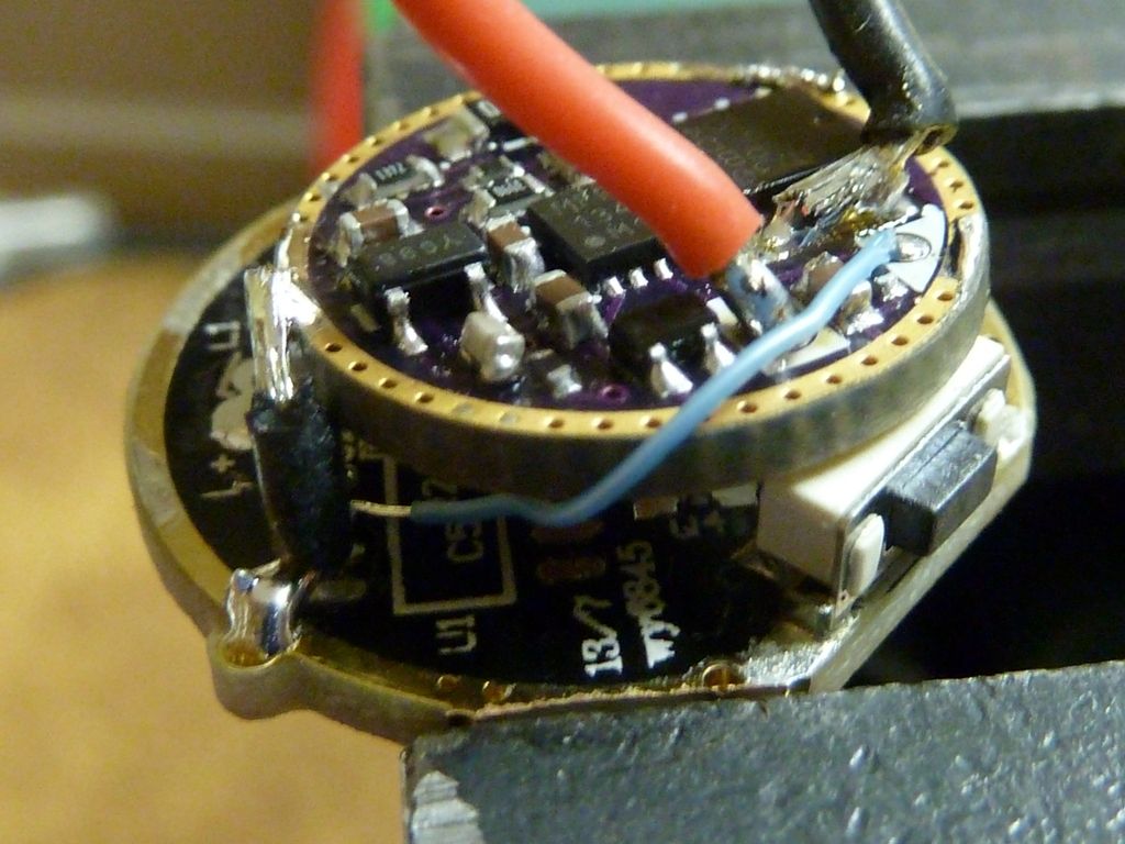
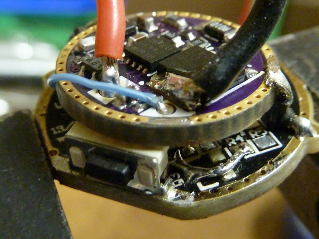
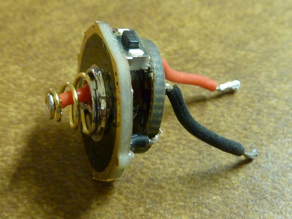
View of the 22 AWG wired up spring:
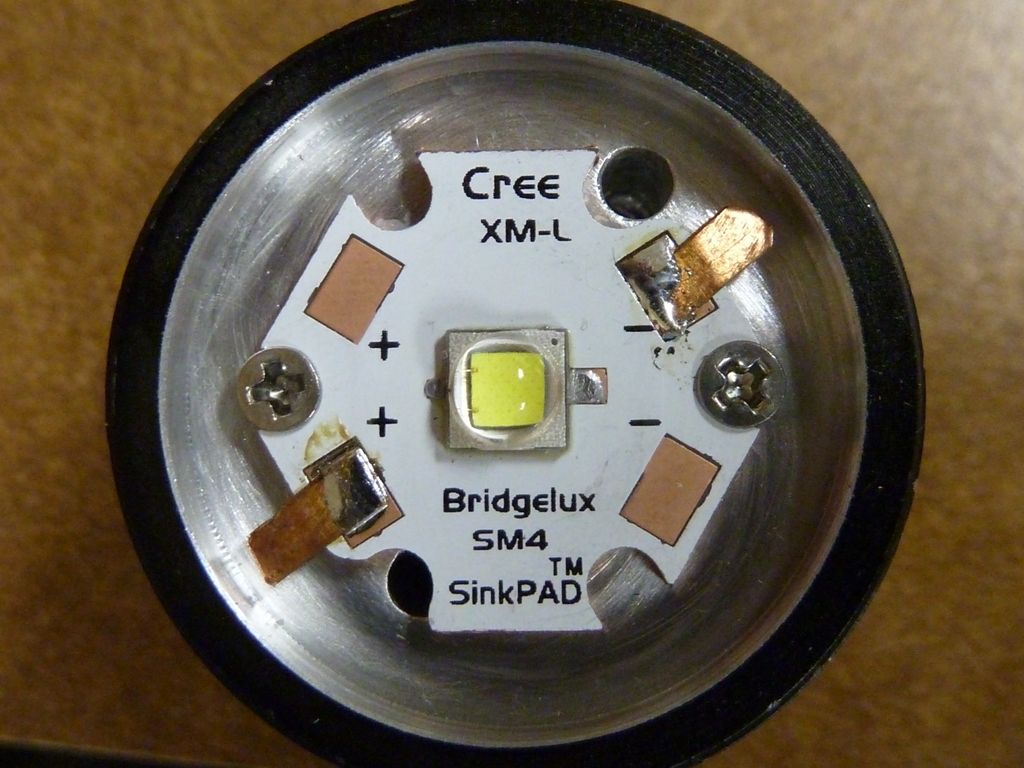
The XM-L2 U2 1D on a 20mm SinkPAD, drilled/tapped holes for screws, add copper sheet metal tabs to extend wires outward:
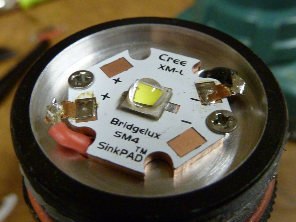
Wired up to the 20 AWG wires:
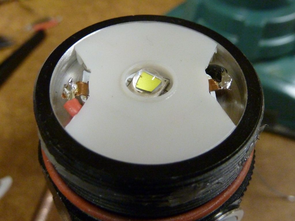
Stock one piece LED alignment piece. I cut out the sides to make room for the tabbed connections:
 I have some R070’s on the way, perhaps replacing that R180 with an R070 would be sufficient to bump output without messing up anything. Or an R068, hmmmm. Do you recall what amperage this driver is making in stock form?

 Pure speculation, but if a MT-G2 at 15A is less efficient than 5 XM-L2's running at the same power (ie watts), doesn't that mean more power gets converted to heat? So, maybe even worse? Think you got a room heater there, forget hand warmer.